Table Saw Router Wing – Table Saw Router Extension
By MMillsWoodworking


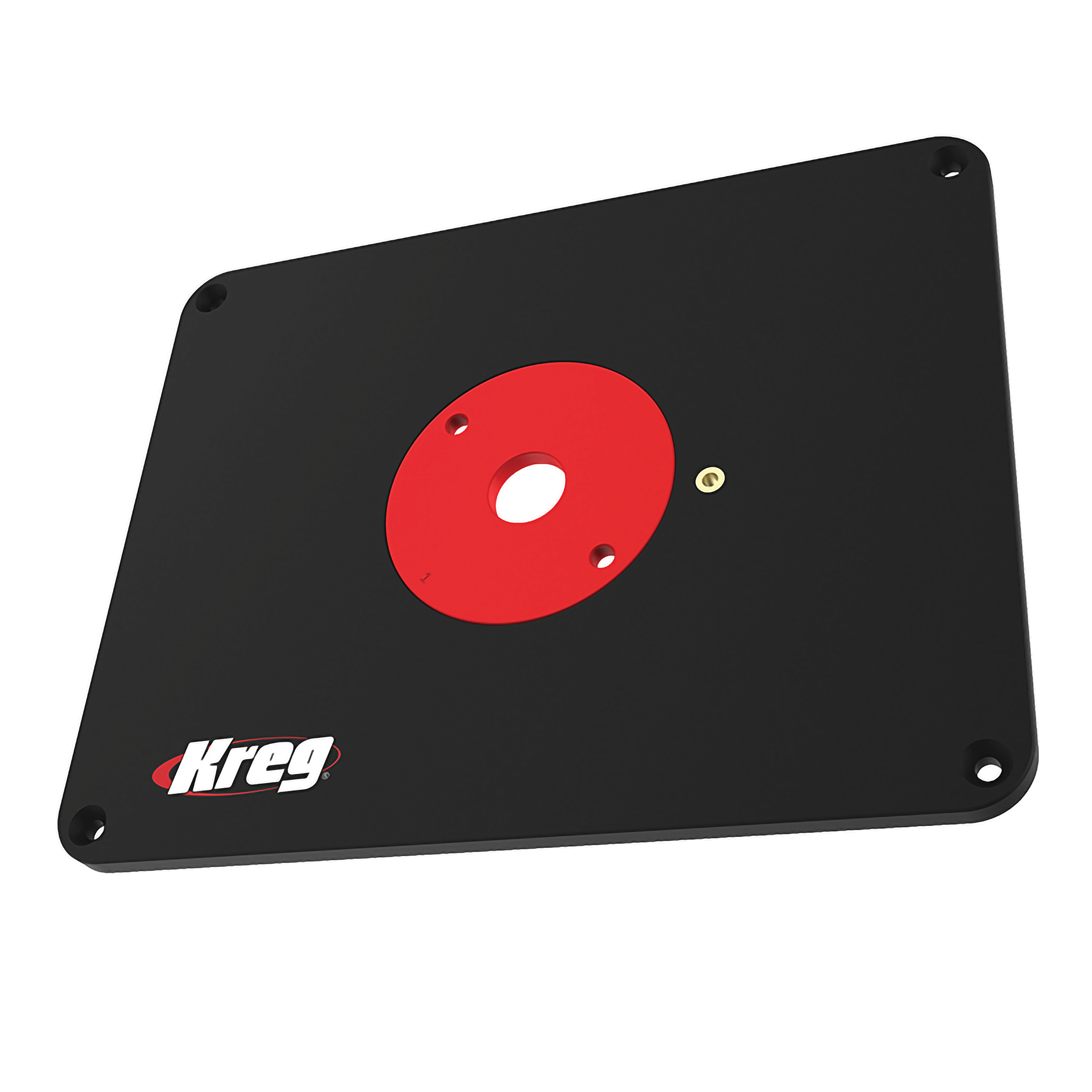
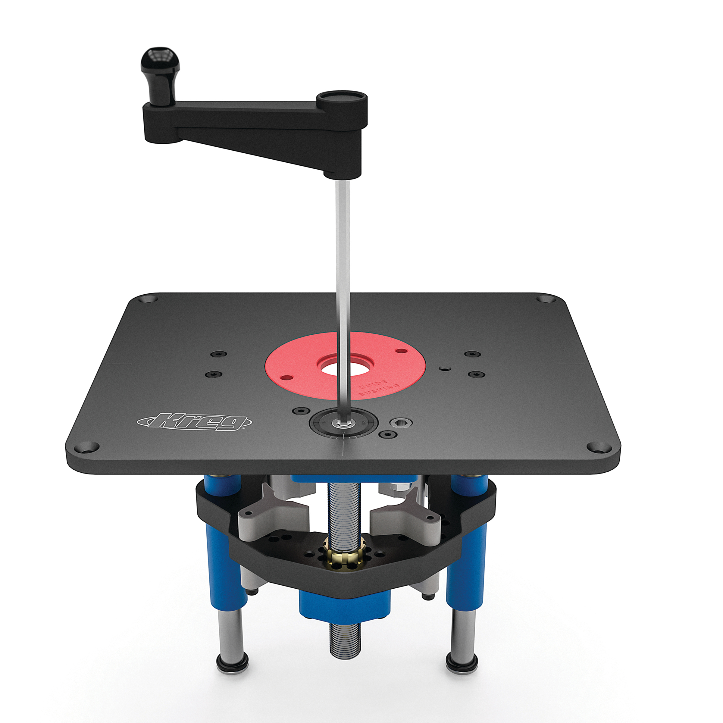
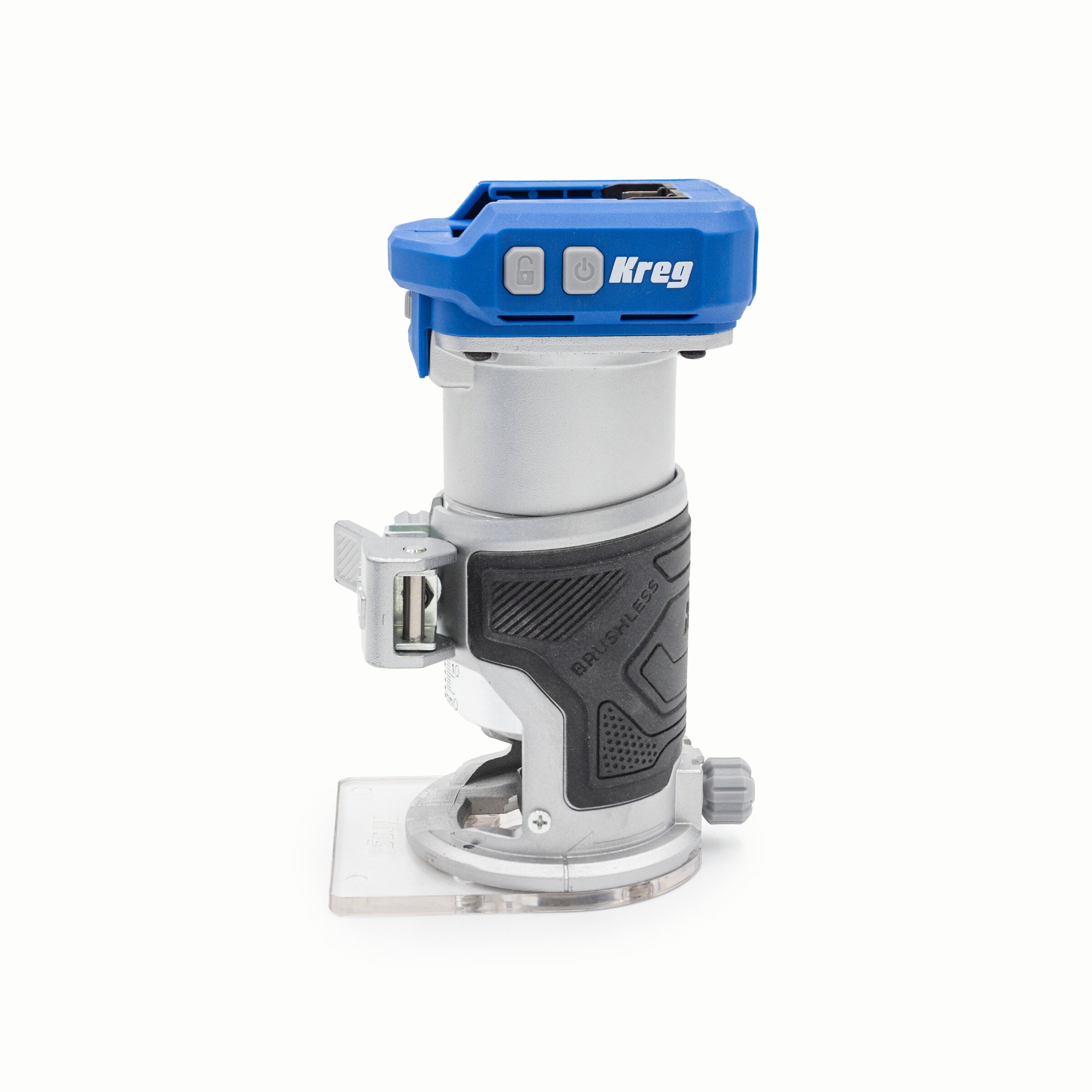
In this project we are adding a router lift into the wing of a table saw. This is a great project if your shop is small, or you do not have the space for a dedicated table. I will be adding a Kreg Router Lift into my Ridgid R4512 table saw.
Tools
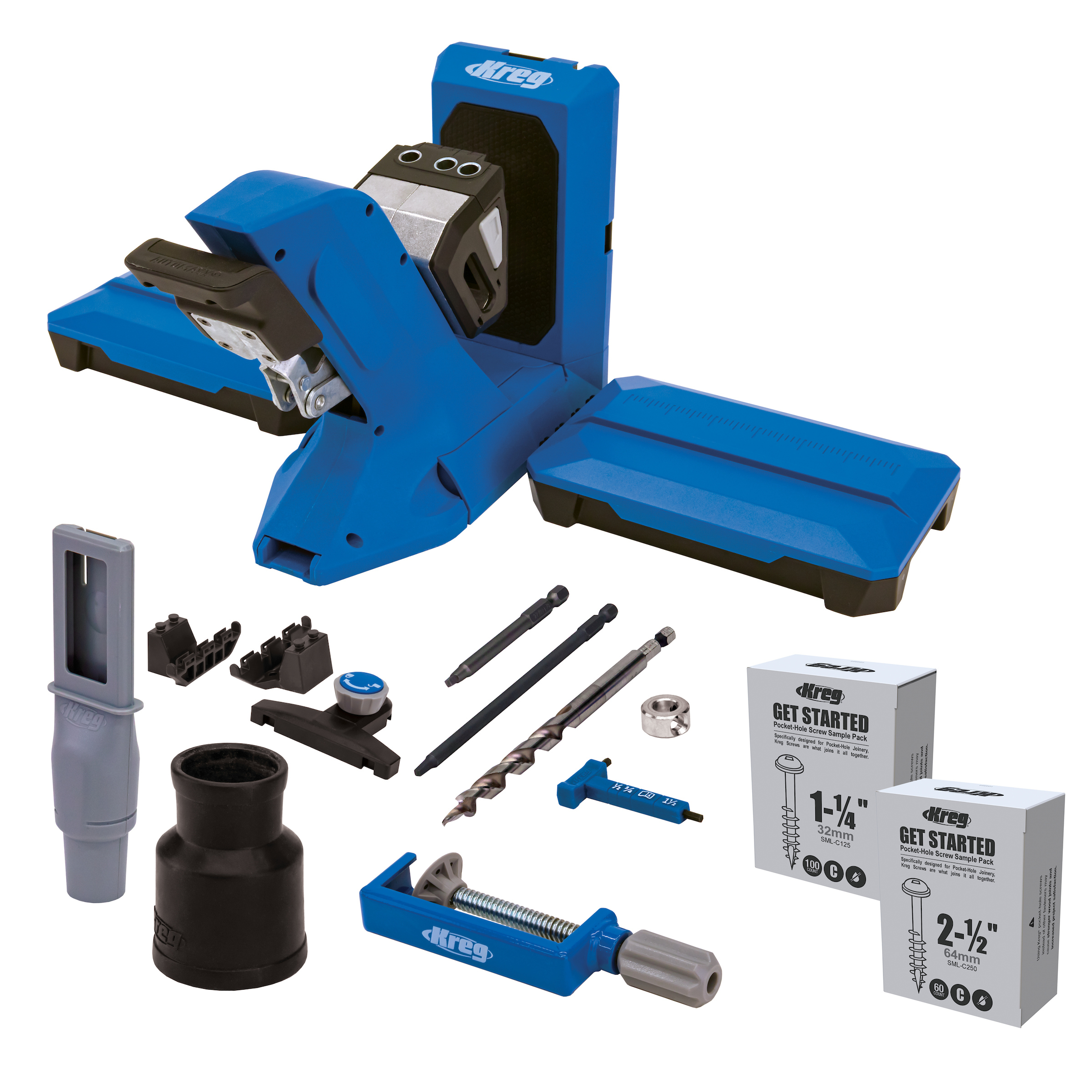
Kreg Tools

Other Tools
-
Table saw or track saw

-
Miter saw
-
Dado stack and table saw
-
Tape measure
-
Clamps
-
Pencil
-
Layout tools
-
Hack saw and files
Materials
Wood Products
- 1 ¾” Plywood (Baltic Birch or something nice and flat) , (at least 30” x 16”)
- 1 1 x 3 Pine , (at least 82”)
- 1 Scrap , ¼” plywood
Hardware & Supplies
- 1 Box pocket hole screws for ¾” soft wood material
- 1 Wood glue
- 1 Box ¾” wood screw
- 1 Double sided tape
Directions
-
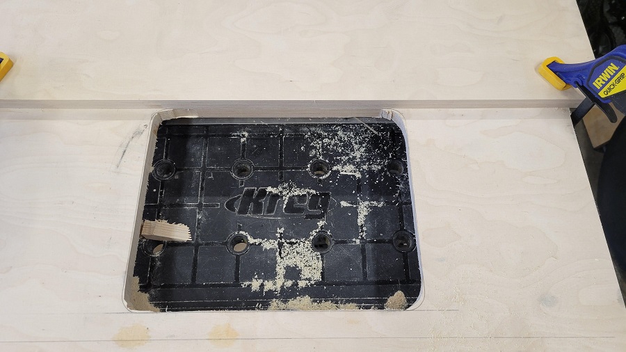
Measure Opening
My opening for my TS (R4512) is 27 1/16” x 14 5/8”. I used a piece of ¾” Baltic Birch Plywood. You can use other materials but cannot go less than ¾”!
-
Cut piece to fit opening
I used my table saw to cut this, but a track saw would work just as well.
Make sure to sneak up to the final dimensions as you do not want to under size this and have it wiggle.
-
Layout the opening for the router lift and the miter/t track slot
I wanted my lift to be about 1 3/4” from the back of the plywood, closest to the table saw side. I then wanted the t track about 1” from the router lift. I laid out the parts on the plywood and marked their locations.
-
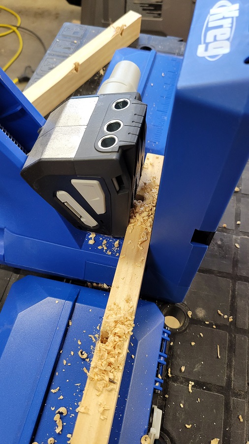
Cut the 1 x 3 reinforcements and drill pocket holes
I used 1x3 and ripped it in half to 1 ¼”. You could use 1 x 2 but it is hard to find nice pieces and I didn’t want it to stick below the table saw wing. I cut mine just a hair short as my table saw has a notch in the back fence.
Drill the pocket holes using your jig.
-
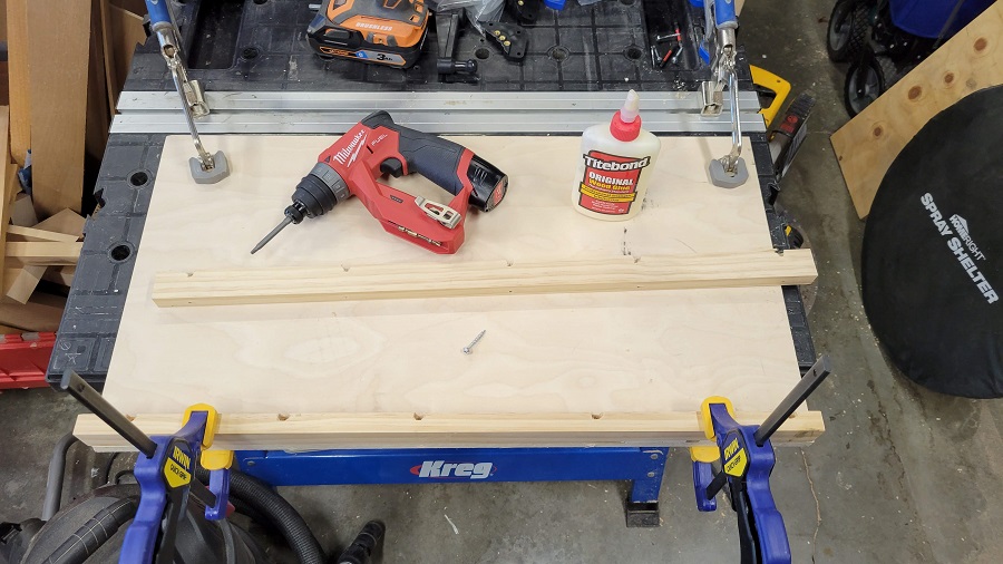
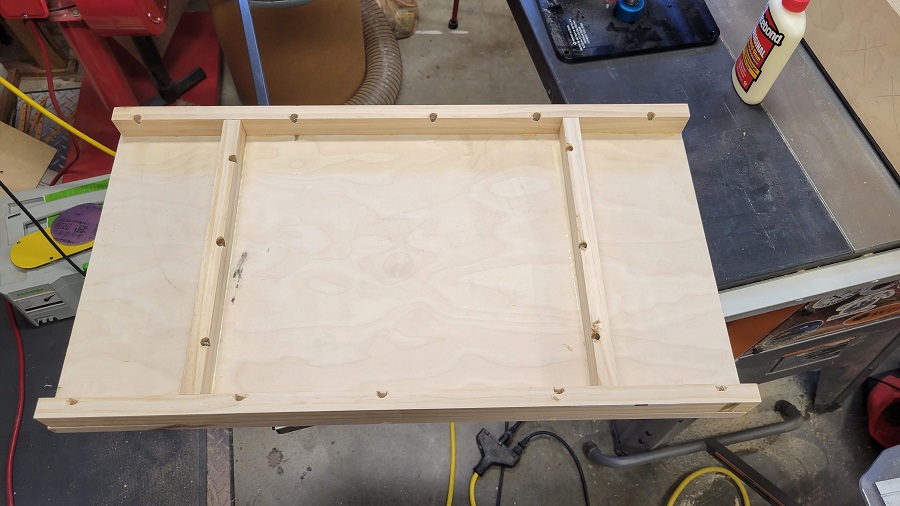
Attach Supports
Use wood glue and attach the supports.
Do this for both sides.
-
Add supports in other direction
We need to add some supports to hold the wing sturdy.
Mine measured about 13 1/8”.
Cut these pieces like the other supports and drill out the pocket holes. Attach using the same steps as previous slide.
I spaced mine in 5 ¼” from the outside edges
-
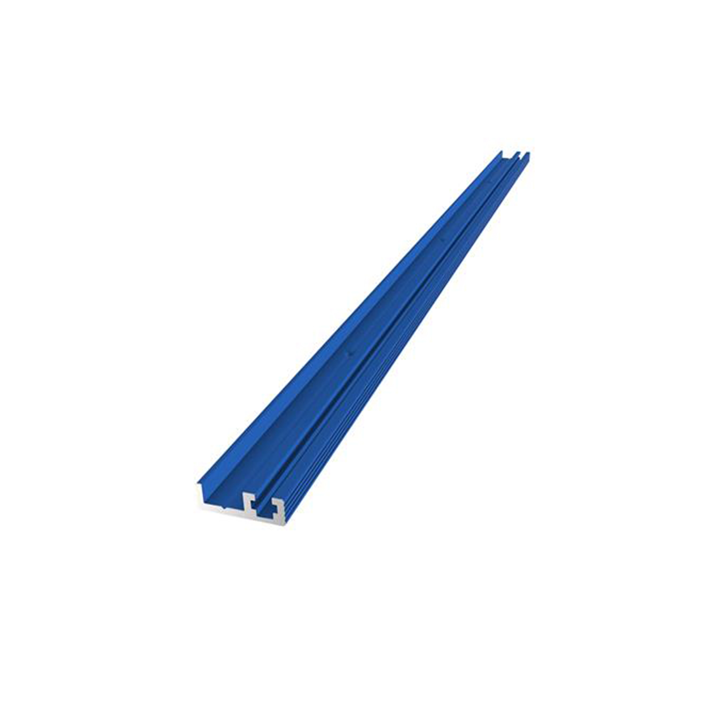
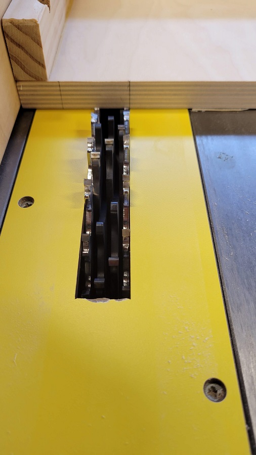
Cut Dado for Combo Track
Next is to cut the recess for the Combo Track. This is about ½” deep by ~1.6”. It is important to test this cut on scraps. You want the combo track barely recessed under the work surface.
I used a dado stack on my table saw and snuck up to the fit by moving the fence a small amount and taking a little off and test fitting.
-
Cut the Combo Track to Length
Once the track recess is cut, mark the place you want to cut the track.
I took off about 1/16” off the total length and left about 1/32” on each side. This is just my preference; you can make it flush if you want.
I used a hack saw for this as it is a pain to set up the liter saw to cut Aluminum and you DO NOT want to use your wood blade for this.
-
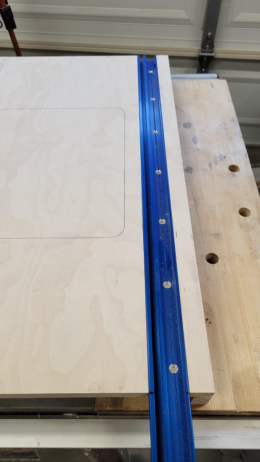
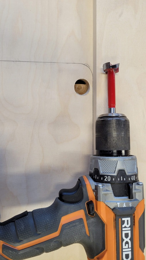
Mount the Combo Track
This is not as straight forward as you would expect. First, I used a centering drill bit, and I would recommend you do as well. They are a great tool to have.
The biggest headache with this is that the screw has very little to bite into. The wood is very thin at this point. You can try and line up the holes in the track to the support, but this would make it such that both ends need to be cut.
I used small #10 screws and set the drill chuck very light. You can add a thin strip of wood under it as well for more grip.
-
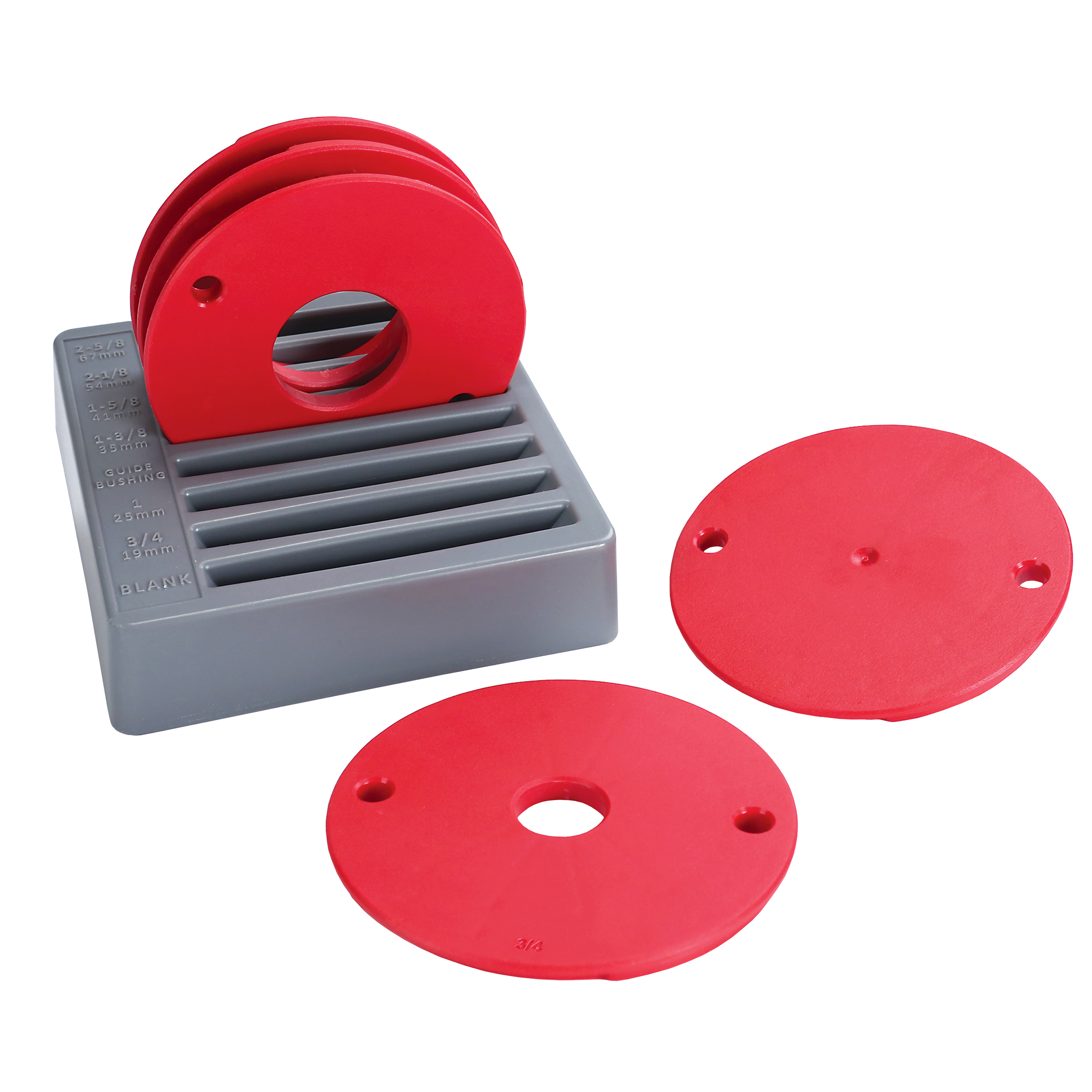
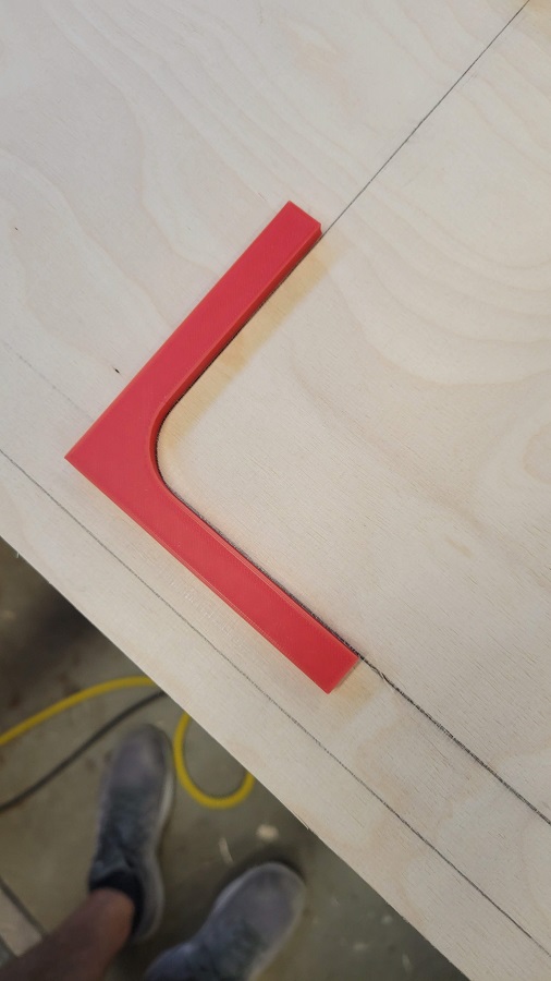
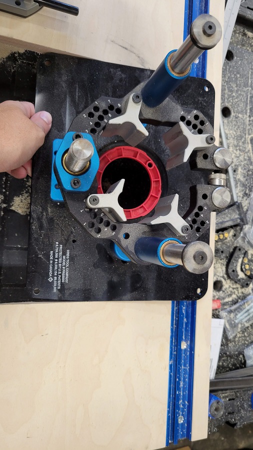
Cutting the Router Insert
This is honestly the hardest part of the build. Some companies sell jigs for this to use a router, I did not opt for that and made a semi-custom jig. I used my 3D printer and made the corner profile. The radius is .750”, so a 1.5” drill bit would do the trick also. But I do not have one that big.
Here is the jig I used:
-
Jig saw the Waste
I am opting to router the hole for the router plate, so you need to jig saw the waste. I went about 1/16” inside of the line.
I honestly forgot to do this and went straight to the router and I messed up the hole. You can see in the pictures. It is important to remove the waste!
For the next steps, the router wing needs to be elevated so the drill bit and router bit are not touching the work bench.
-
Routing the Straight Sections
For this step I used my Plunge Router and a pattern bit (flush cutting bit) and some straight plywood. It is important to get a piece big enough so the router is stable. After I straight edge piece clamped in place, I set the depth of the router to ride on the straight edge but cut the whole profile.
-
Routing the Straight Sections
Do this for all four straights. Do not get too close to the curves as this will be done in the next step.
For the straight closest to the back (non-combo track side), I had to use a straight edge guide and a spiral cutting bit. You can use a scrap piece of plywood, but it is very close to the edge. I took small cuts off this one and test fit the plate to ensure the fit was snug.
I would test fit all sides just to be safe.
-
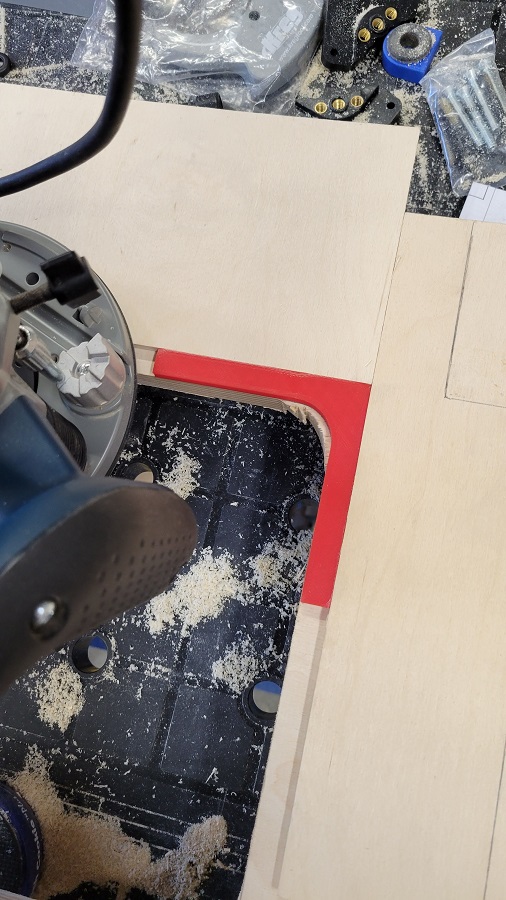
Routing the Curves
This is where my 3D printed jig comes into play. If you have the drill bit for cut this, you can do that now or before taking out the router.
I will also use some ¼” plywood scraps to hold up the router base around the jig. I used double sided tape and clamps to hold the pieces down.
Do this for all 4 sides.
-
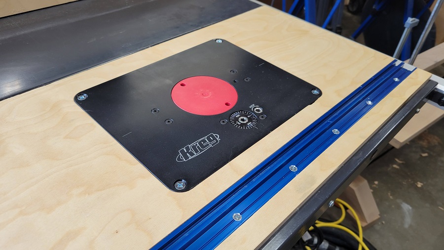
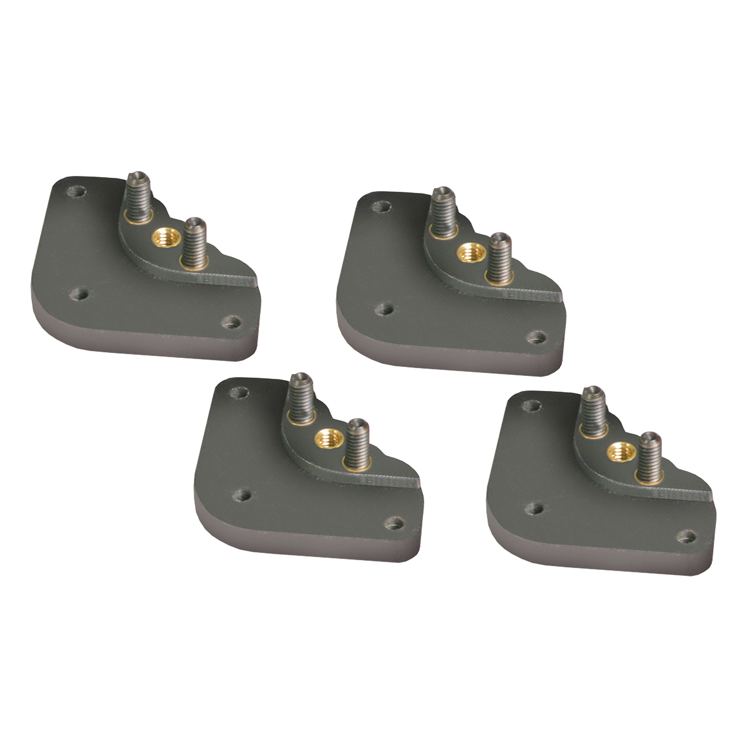
Installing the Router Plate Feet
For this step, I wanted to use the stock hardware, but the screws were too long and would have protruded out the top. I had to use some ¾” wood screws instead. Install all four into the corners.
I also installed the set screws on each foot since it is at eye level and easy to see. You do not need to do this, but it may be helpful.
-
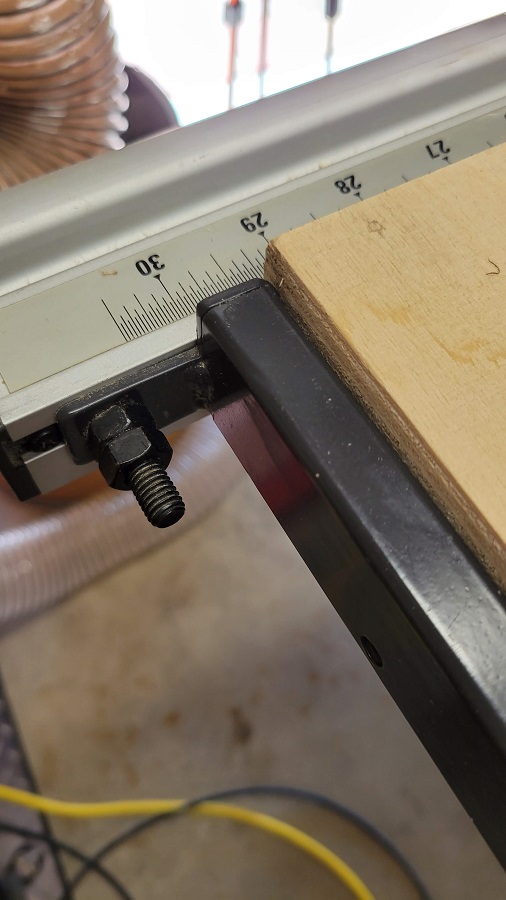
Installing the Router Wing into the Saw
Finally getting to installing the wing! Before you drill it in, check to make sure your work surface is flat, mine was not!
Once the table saw wing was flat, I used the same levels to make sure the wing was flat. I used the pocket hole screws to install this as they do a very good job of sucking the wood back onto the metal table saw and the head is nice and large to get a tight fit.
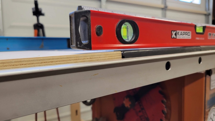
-
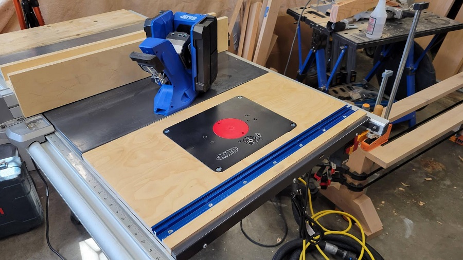
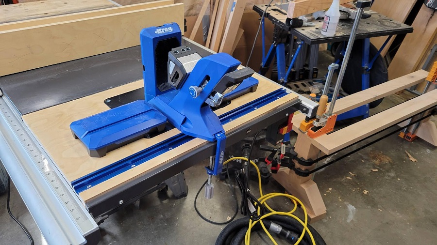
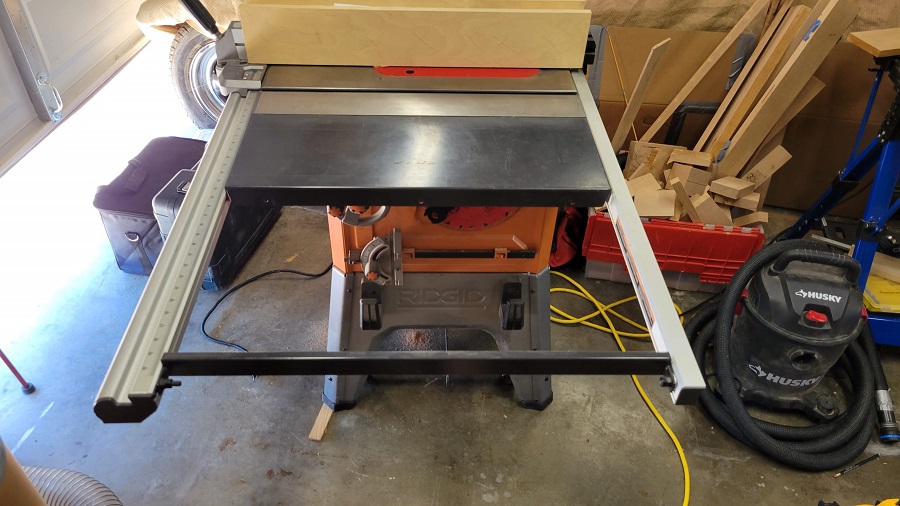
Finishing Touches!
The router wing is installed!
Some nice finishing touches that can be done:
- Sand and finish the surface so it is smooth
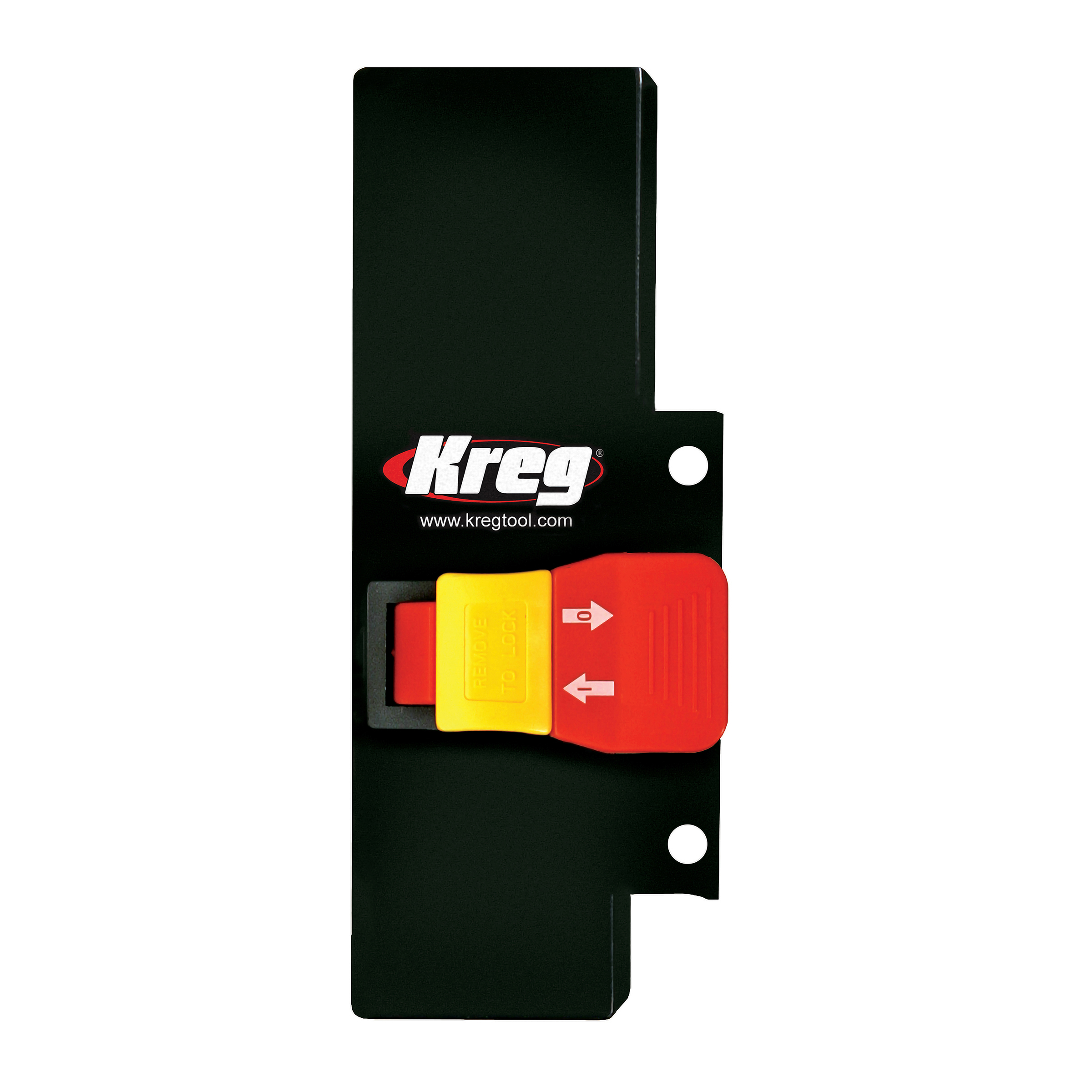
- Add the Router Switch
- Cable Management
- Level the router plate to the surface and install flat head screws