DIY Miter Saw Stand – How To Build a Rolling Miter Saw Stand
By Kreg Tool

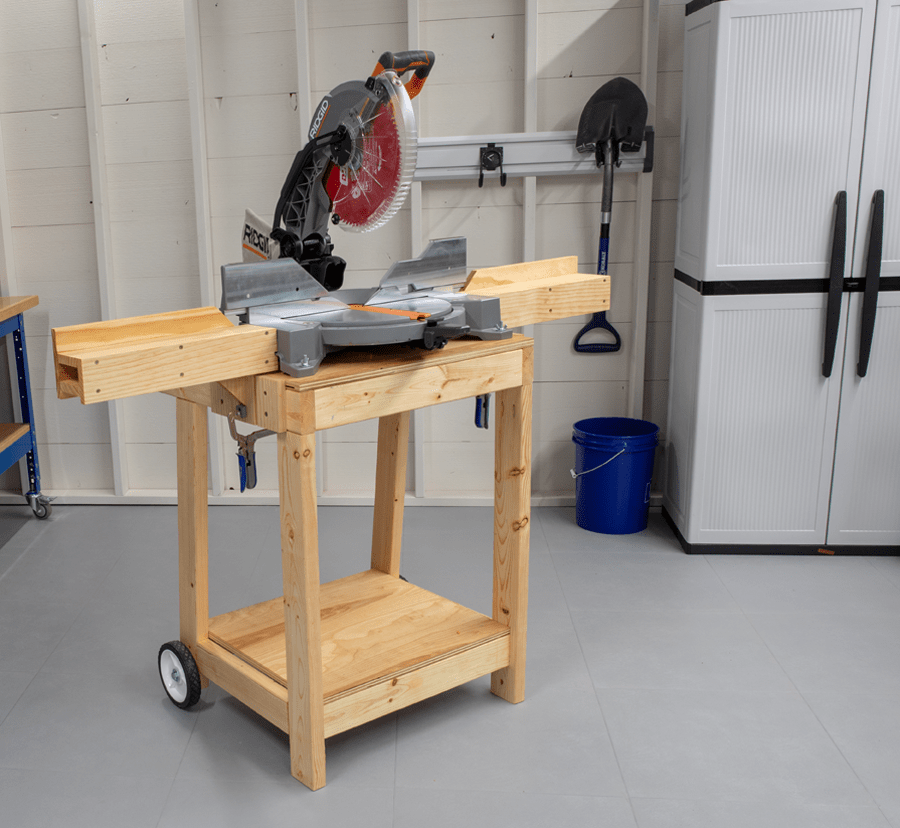
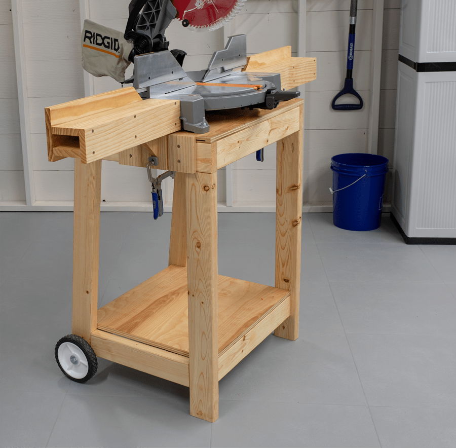
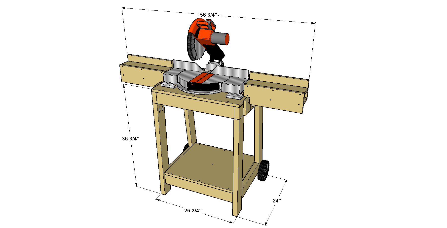


Building this project will make your other DIY projects easier to build. This miter saw stand gives a home to one of your most important tools. It offers removable support wings to hold long boards. Plus, this miter saw stand rolls easily to work where you want to, and then tuck compactly away.
Tools
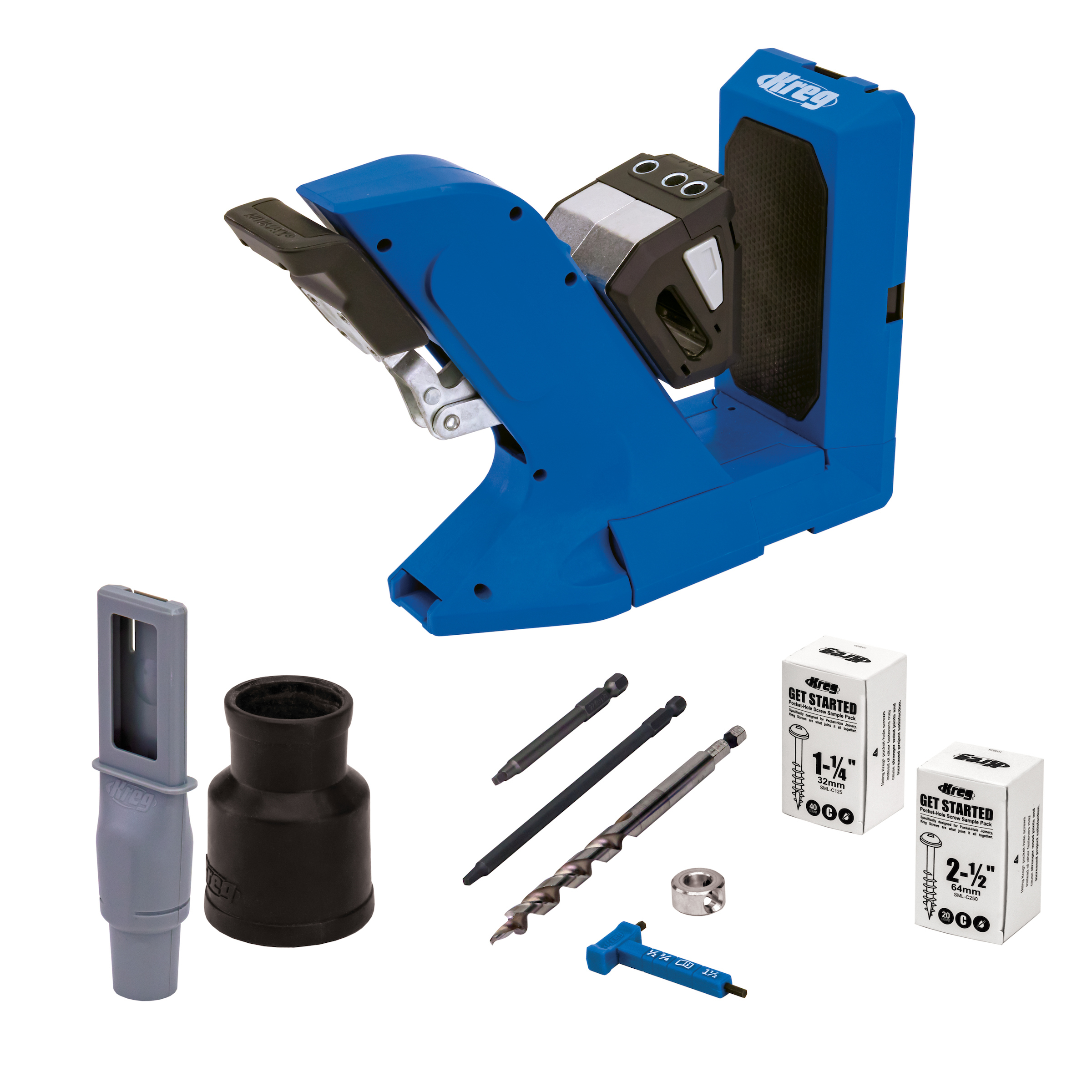
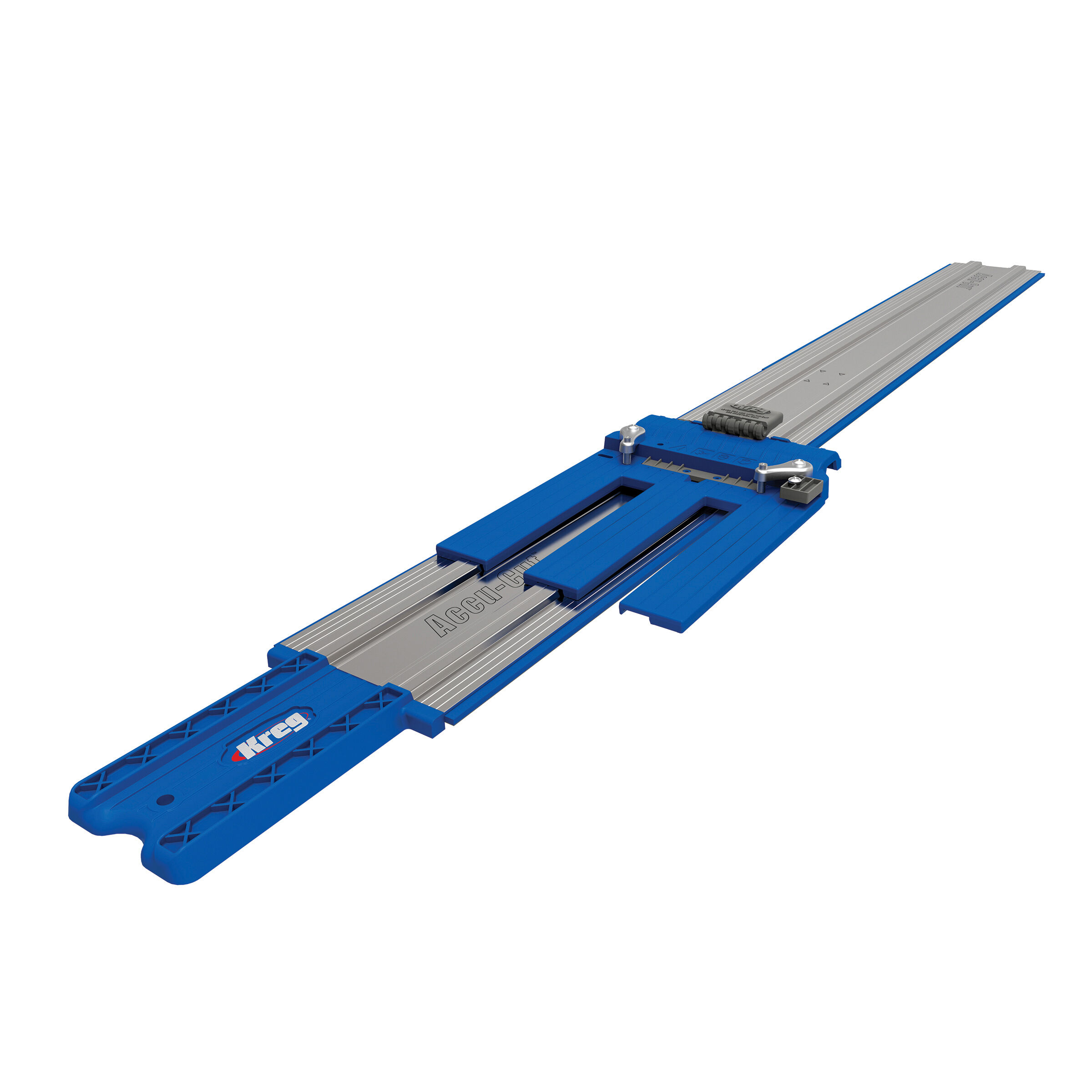
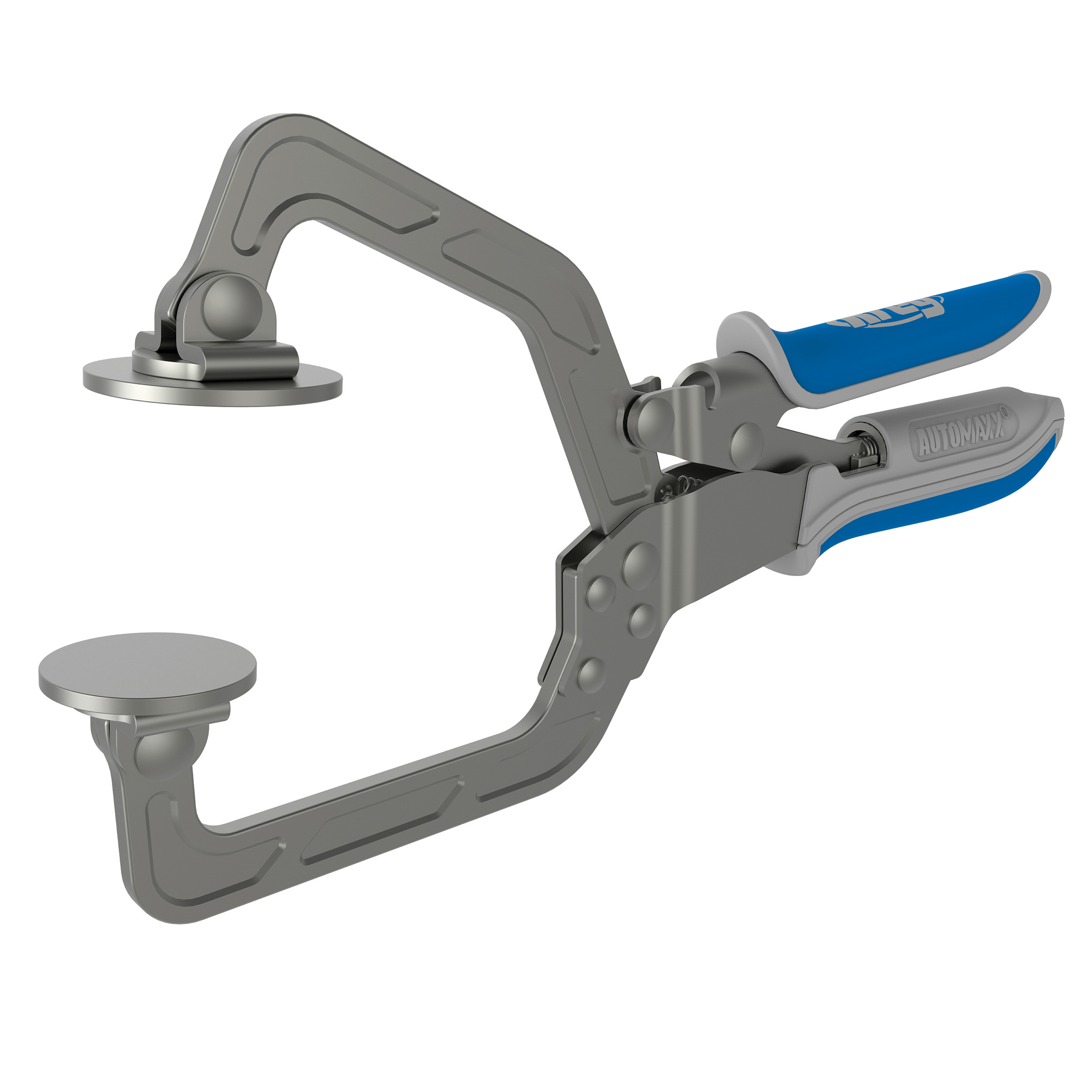
Kreg Tools

Other Tools
-
miter saw

-
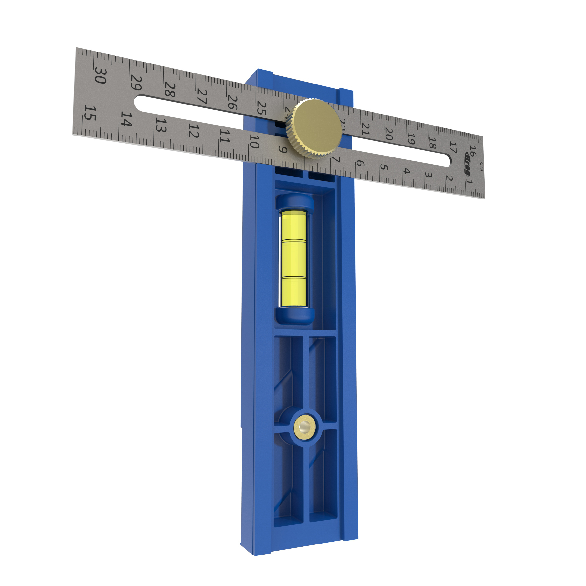
tape measure
Materials
Wood Products
- 4 Board , 2x4 x 96"
- 2 Board , 1x4 x 72"
- 1 Board , 1x6 x 48"
- 1 Plywood , 3/4" x 24" x 48"
- 1 Dowel , 1" x 48"
Hardware & Supplies
- 36 2 1/2" Kreg Pocket-Hole Screws
- 65 1 1/4" flat-head wood screw
- 2 7" lawnmower replacement wheel
- 2 1/2" x 4 1/2" hex-head bolt
- 4 1/2" fender washer
- 2 1/2" washer
- 2 1/2" nylon locknut
- 4 5/16" x 2 1/2" hex-head bolt
- 8 5/16" washers
- 4 5/16" wingnut
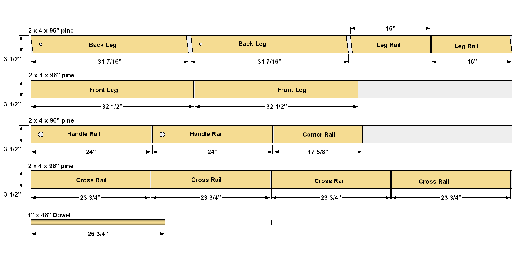
Cut List & Parts
- 2 Front Leg , 1 1/2" x 3 1/2" x 32 1/2"
- 2 Back Leg , 1 1/2" x 3 1/2" x 31 7/16"
- 2 Leg Rail , 1 1/2" x 3 1/2" x 31 7/16"
- 2 Handle Rail , 1 1/2" x 3 1/2" x 24"
- 4 Cross Rail , 1 1/2" x 3 1/2" x 23 3/4"
- 1 Center Rail , 1 1/2" x 3 1/2" x 17 5/8"
- 1 Shelf , 3/4" x 20 5/8" x 23 3/4"
- 1 Top , 3/4" x 20" x 26 3/4"
- 1 Handle , 1" x 26 3/4"
- 2 Wing Base , 3/4" x 3 1/2" x 20"
- 2 Wing Support , 3/4" x 3 1/2" x 4 1/4"
- 2 Angle Brace , 3/4" x 3 1/2" x 3 1/2"
- 2 Fence Back , 3/4" x 5 1/2" x 16"
- 2 Fence Front , 3/4" x 5 1/2" x 16"
- 2 Fence Top , 3/4" x 3 1/2" x 16"
- 4 Wing Stop , 3/4" x 3 1/2" x 4 1/4"
Directions
-
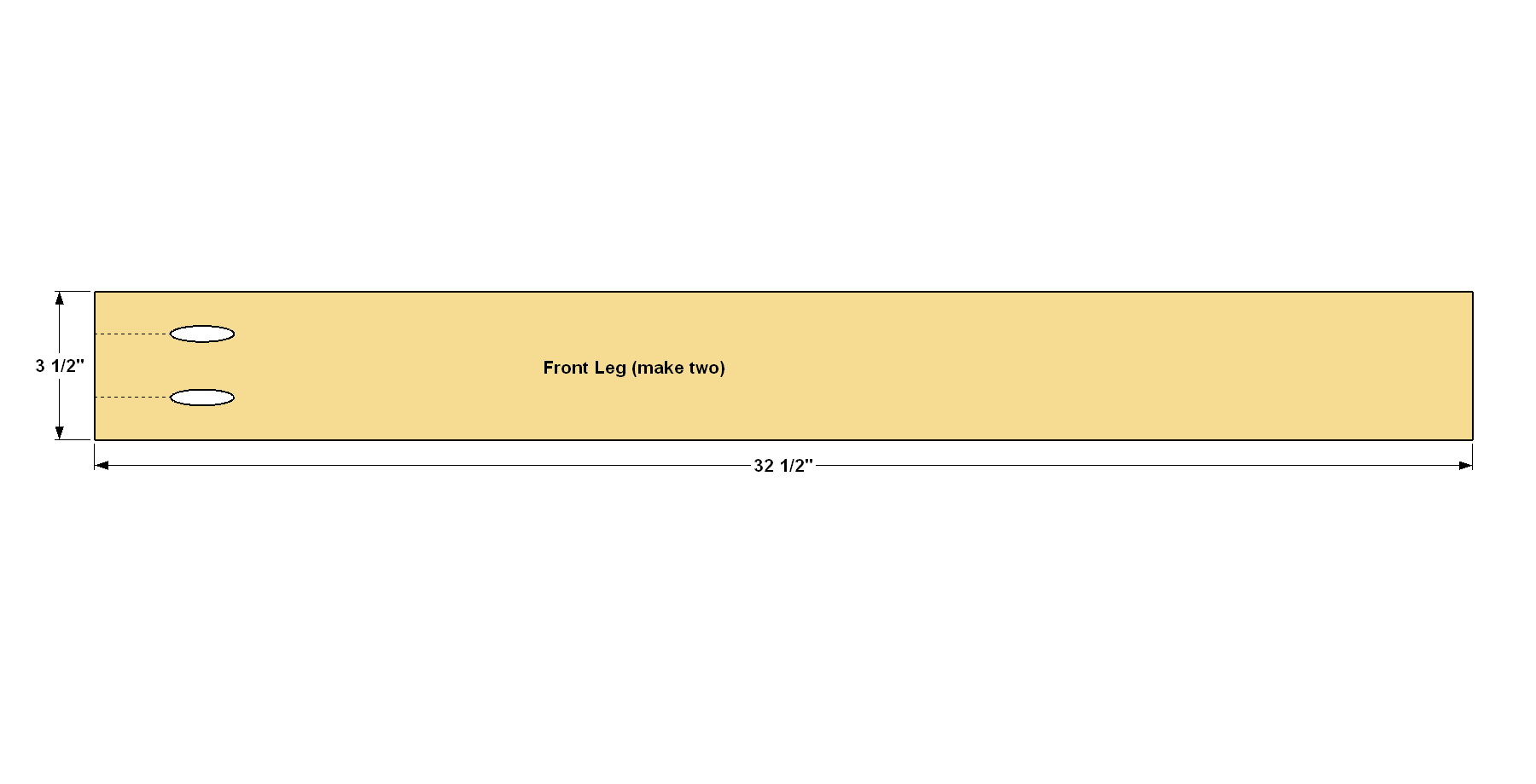
Make the Front Legs
Start by cutting the two Front Legs to length from a 2x4, as shown in the cutting diagram. To drill the pocket holes, set your Kreg® Pocket-Hole Jig for 1 1/2" material. Drill pocket holes at the locations shown.
-
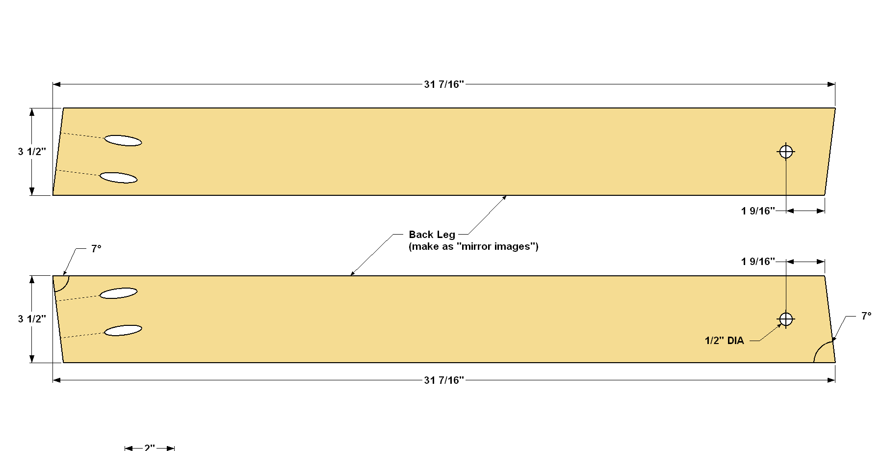
Make the Back Legs
Cut the two Back Legs to size from a 2x4, as shown in the cutting diagram. Notice that ends have parallel 7° angle cuts. Drill pocket holes at the locations shown. When doing this, position the Back Legs as “mirror images” so that you drill the pocket holes in the inside face of each one. Now clamp one Back Leg on top of the first so that the ends are aligned. Then drill a hole through both Legs, where shown, for the wheel bolts.
-
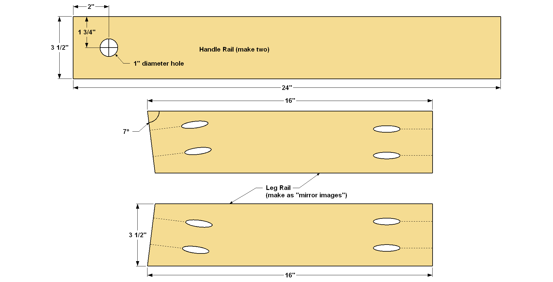
Make the Handle and Leg Rails
Cut two Handle Rails to length from a 2x4, as shown in the cutting diagram. Clamp the Handle Rails together, mark the location of the handle hole, and drill a 1" hole through both Handle Rails. Next, cut two Leg Rails to length from a 2x4, as shown in the cutting diagram. Note that one end has a 7° angle. Position the Leg Rails as “mirror images,” as you did with the Back Legs in Step 2. Now, drill pocket holes on the inside faces of each Leg Rail, as shown.
-
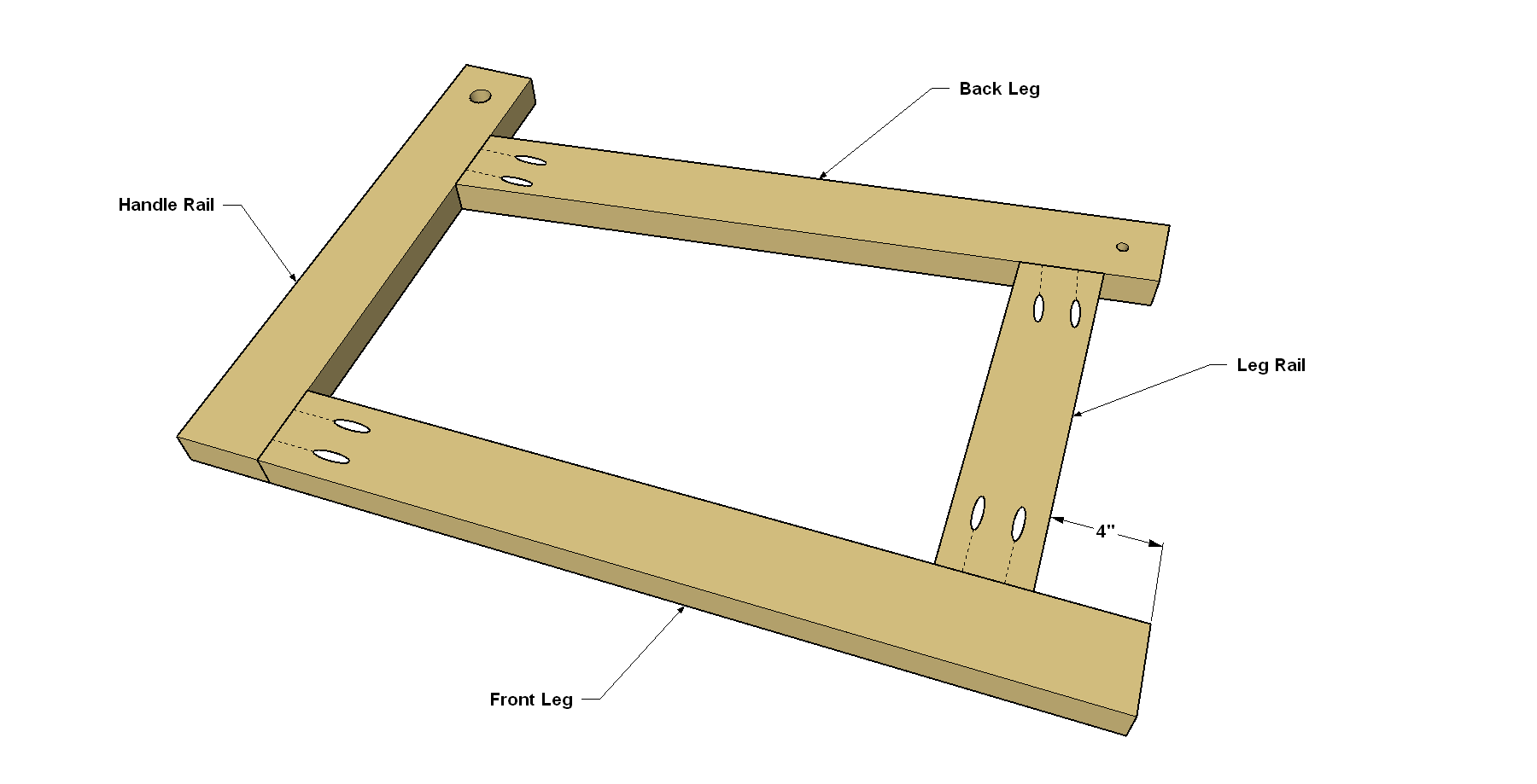
Assemble the Sides
To assemble one side, position one Handle Rail, Leg Rail, and the Front and Back Leg as shown. First, attach the Front Leg to the Handle Rail using 2 1/2" Kreg Pocket-Hole Screws. Next, position the Leg Rail on the Front Leg, at the position shown, and attach it using 2 1/2" Kreg Pocket-Hole Screws. Finally, bring the Back Leg into final position, and then attach it to the Front and Back Legs as shown. Repeat the process for the other side.
-
Cut the Handle
Cut the Handle to length from a 1" poplar dowel, as shown in the cutting diagram.
-
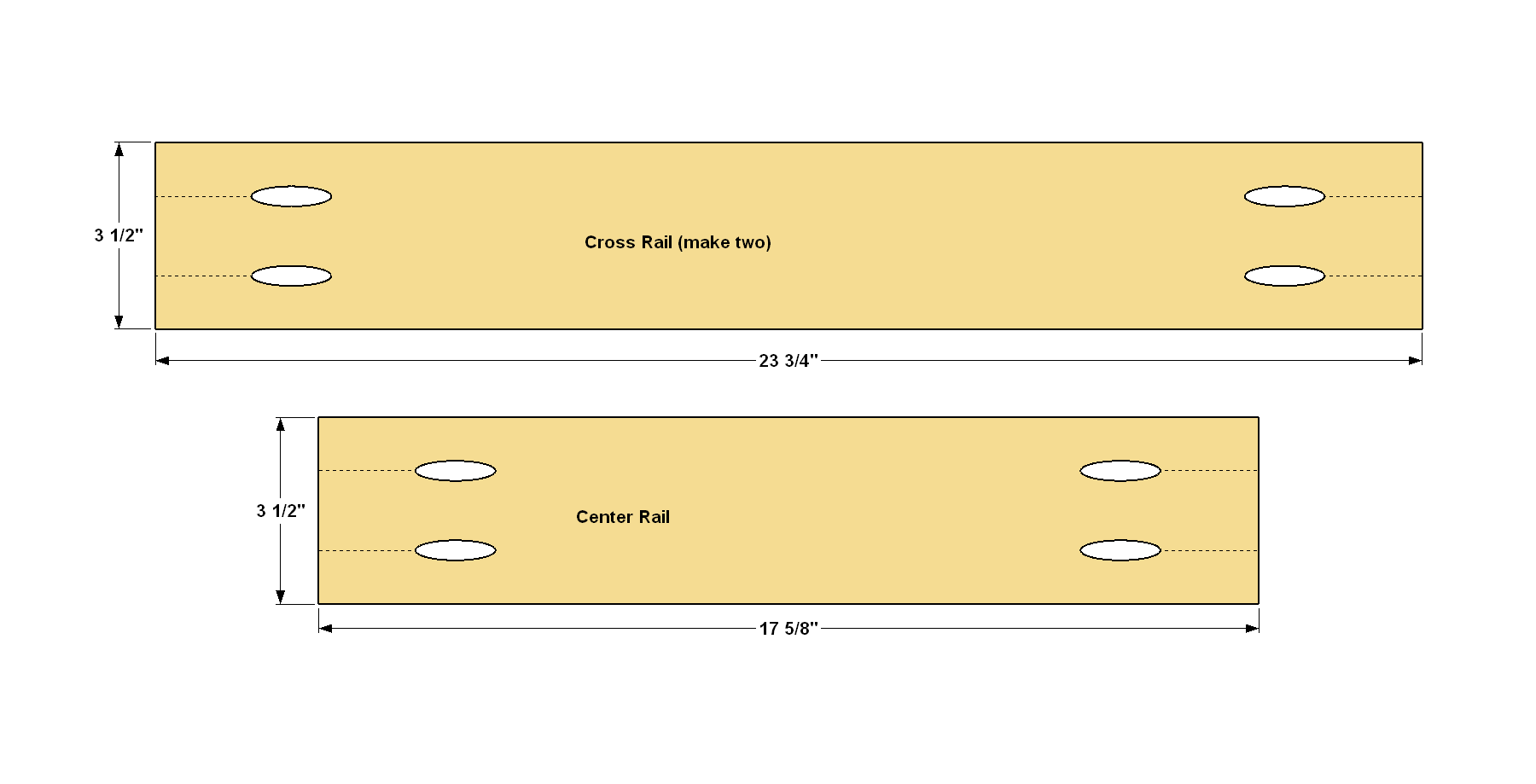
Make the Rails
Cut four Rails and one Center Rail to length from a 2x4, as shown in the cutting diagram. Drill pocket holes in each part at the locations shown.
-
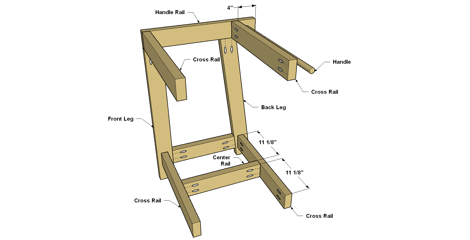
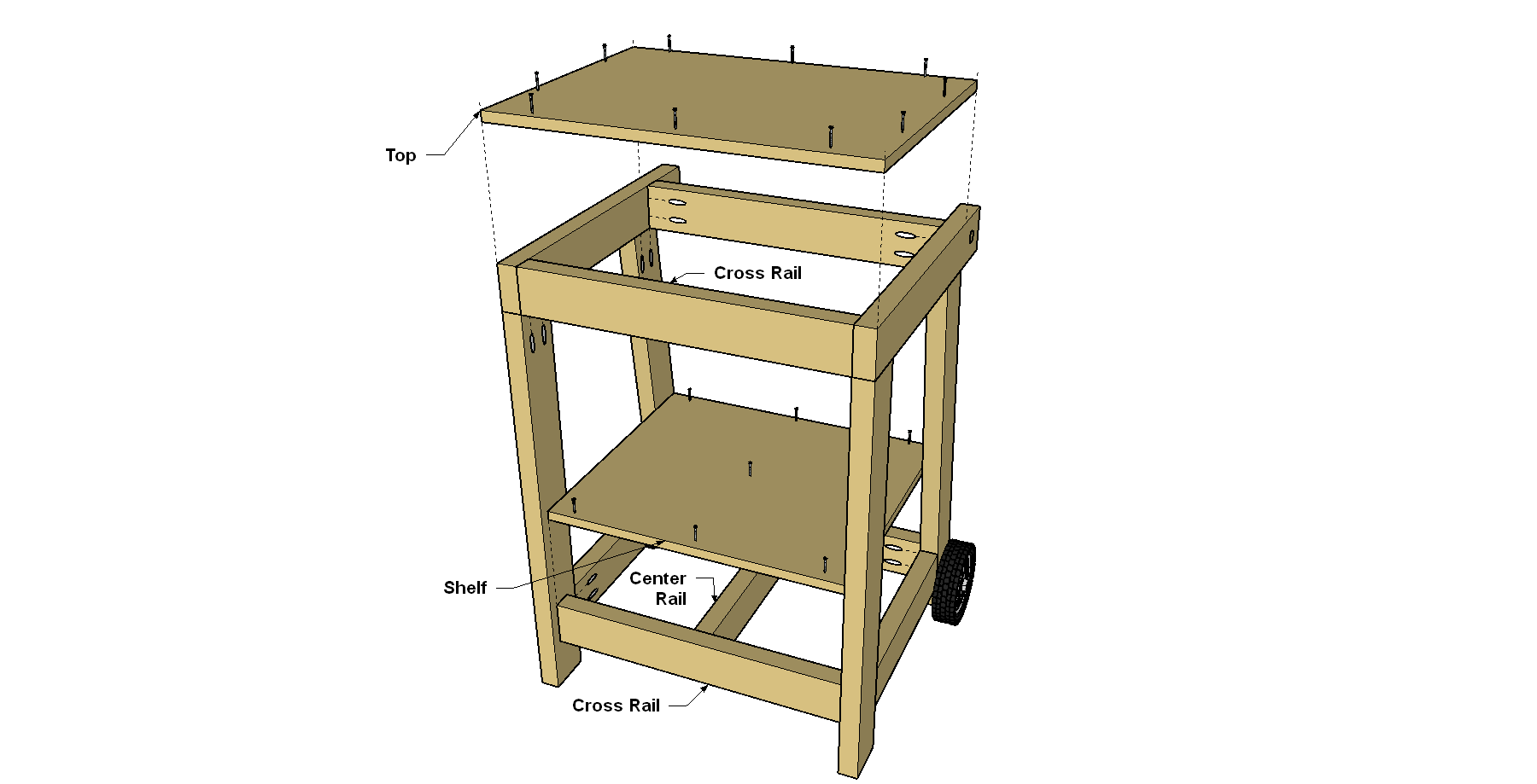
Assemble the Base
Position the four Rails against a side assembly, as shown. Then attach the Rails using 2 1/2" Kreg Pocket-Hole Screws. Next, attach the Center Rail in between the two Lower Rails, as shown. Slip the Handle into its hole in the Handle Rail. Position the second side assembly, and then attach it to complete the base.
-
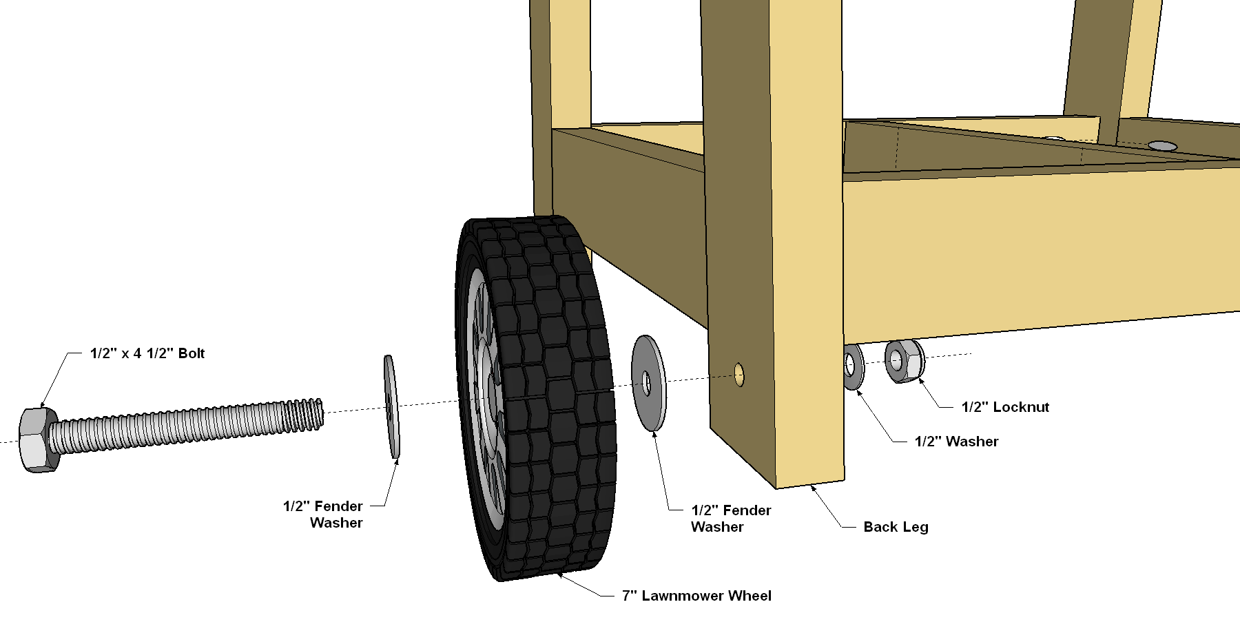
Mount the Wheels
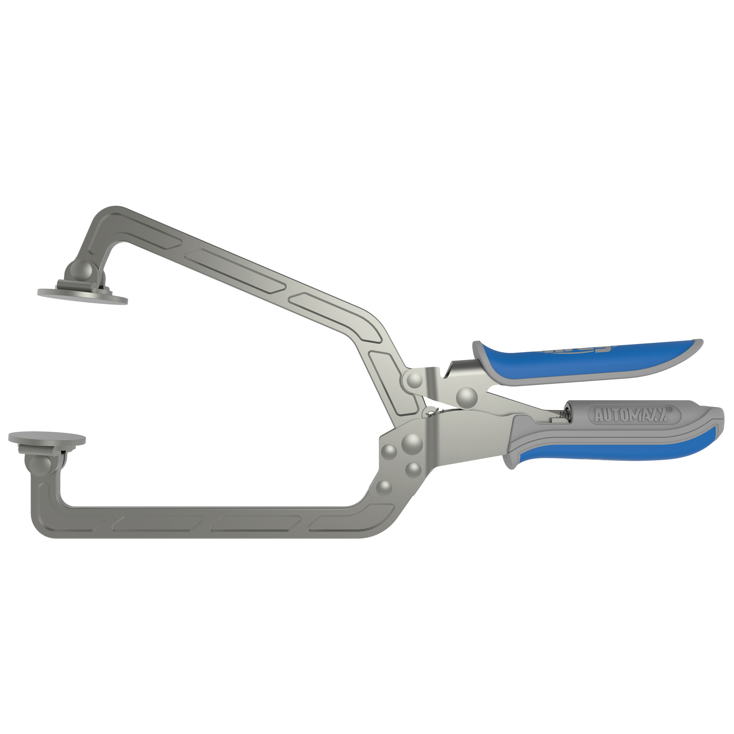
Place one fender washer over a wheel bolt, add a wheel, and then add a second fender washer. Slide the wheel and bolt through the hole in the Back Leg, as shown. Finally, add a standard 1/2" washer, and then the nylon locknut to secure the first wheel. Repeat the process for the second wheel.
-
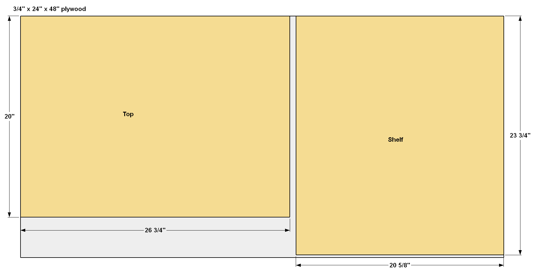
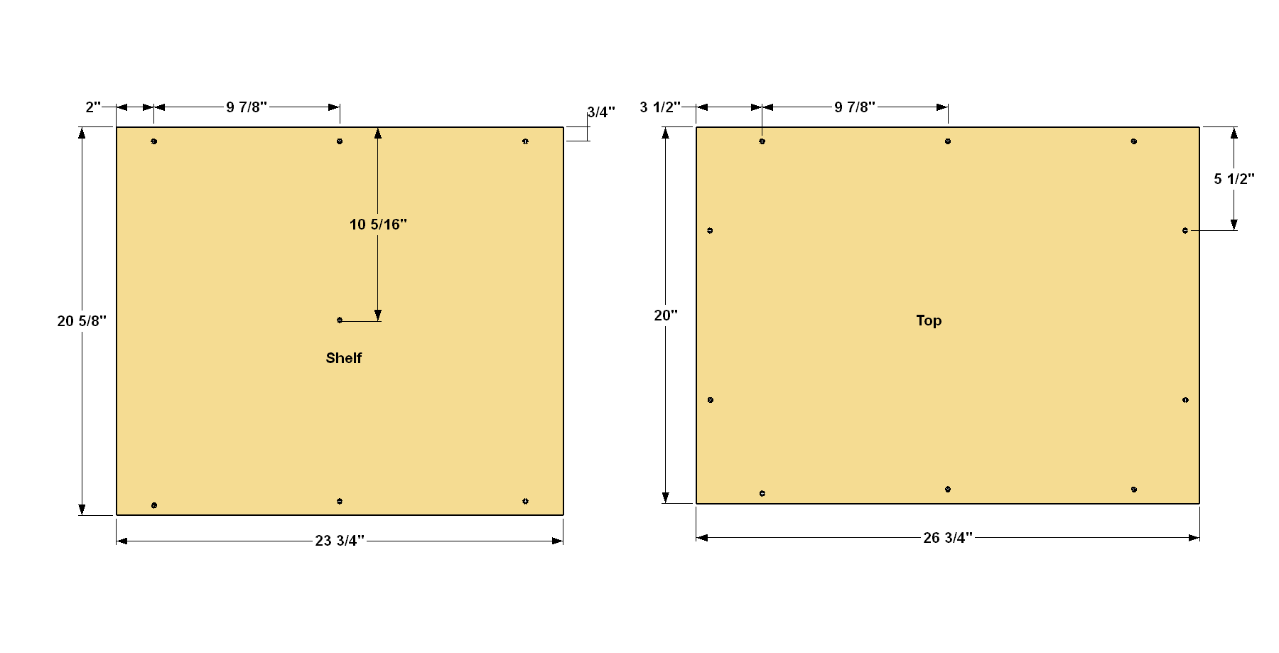
Make the Top and Shelf
Cut the Top and Shelf to size from 3/4" plywood as shown in the cut diagram. Then lay out and drill 1/8" pilot holes, where shown. Countersink the holes so the screw heads will sit flush when you attach the Top and Shelf to the Base in the next step.
-
Attach the Top and Shelf
Position the Top on the Base so it is flush on each side, as shown. Then screw the top to the frame using 1 1/4" flat-head wood screws. Then position the Shelf, and attach it, as well.
-
Mount Your Saw to the Base
Every miter saw is different in both size and shape. These next steps will have to be adjusted to fit your saw. Place your saw on the base and center it side to side. Adjust the position front to back to where it feels comfortable for you. Make sure the saw’s fence is parallel to the front edge of the miter saw stand’s Top. With a pencil, mark the location of each mounting hole in the base of the saw. Verify the diameter of bolt that will easily fit thorough the mounting hole (5/16" in our case), remove the saw from the base, and drill the holes. Place the saw back on the base, and then secure it with bolts and washers. We used wing nuts so we can easily remove the saw if we need to.
-
Get Set to Make the Support Wings
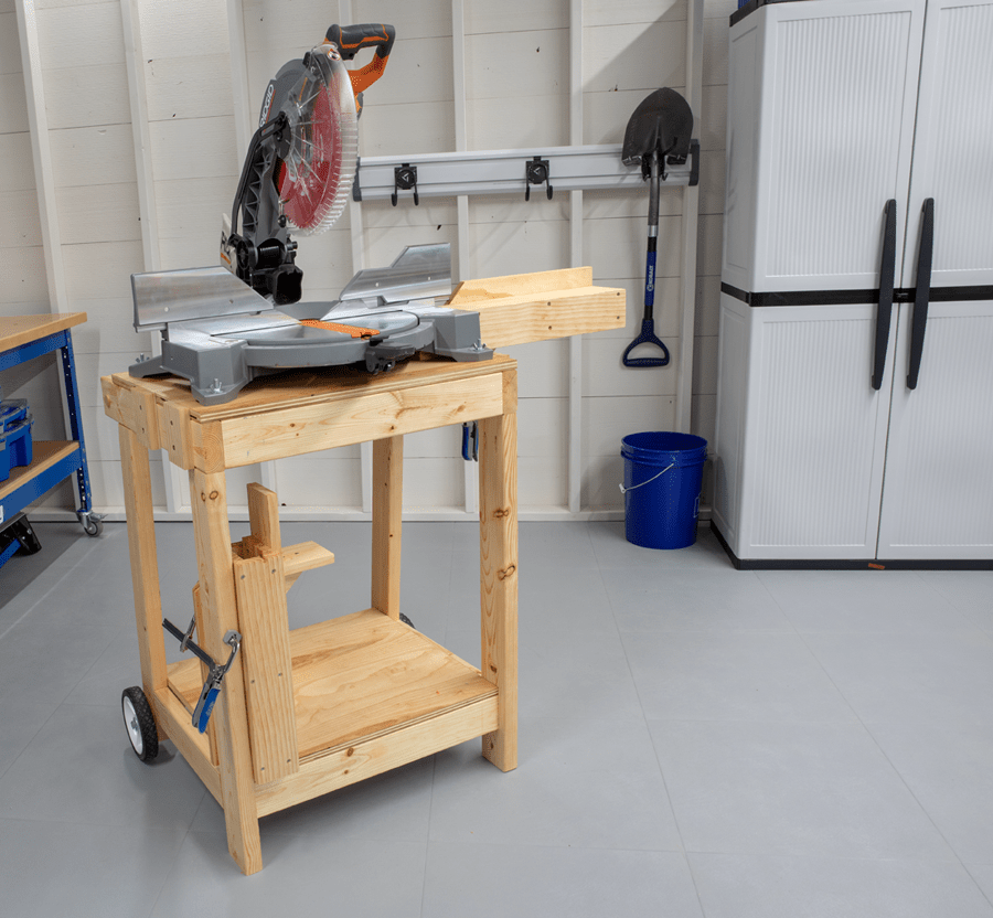
We added removable support wings/fences on each side of the miter saw stand to help hold long boards while cutting If you wish to add them, that comes next. The challenge here is that every miter saw is different—some are wider than others, and the saw tables often sit at different heights. That means you need to customize the wings. Our design makes that possible, by letting you cut the parts, and then adjust their mounting positions to set the placement and overall height of the wings. Just be sure to take your time and measure carefully as you cut and fit your wing parts.
-
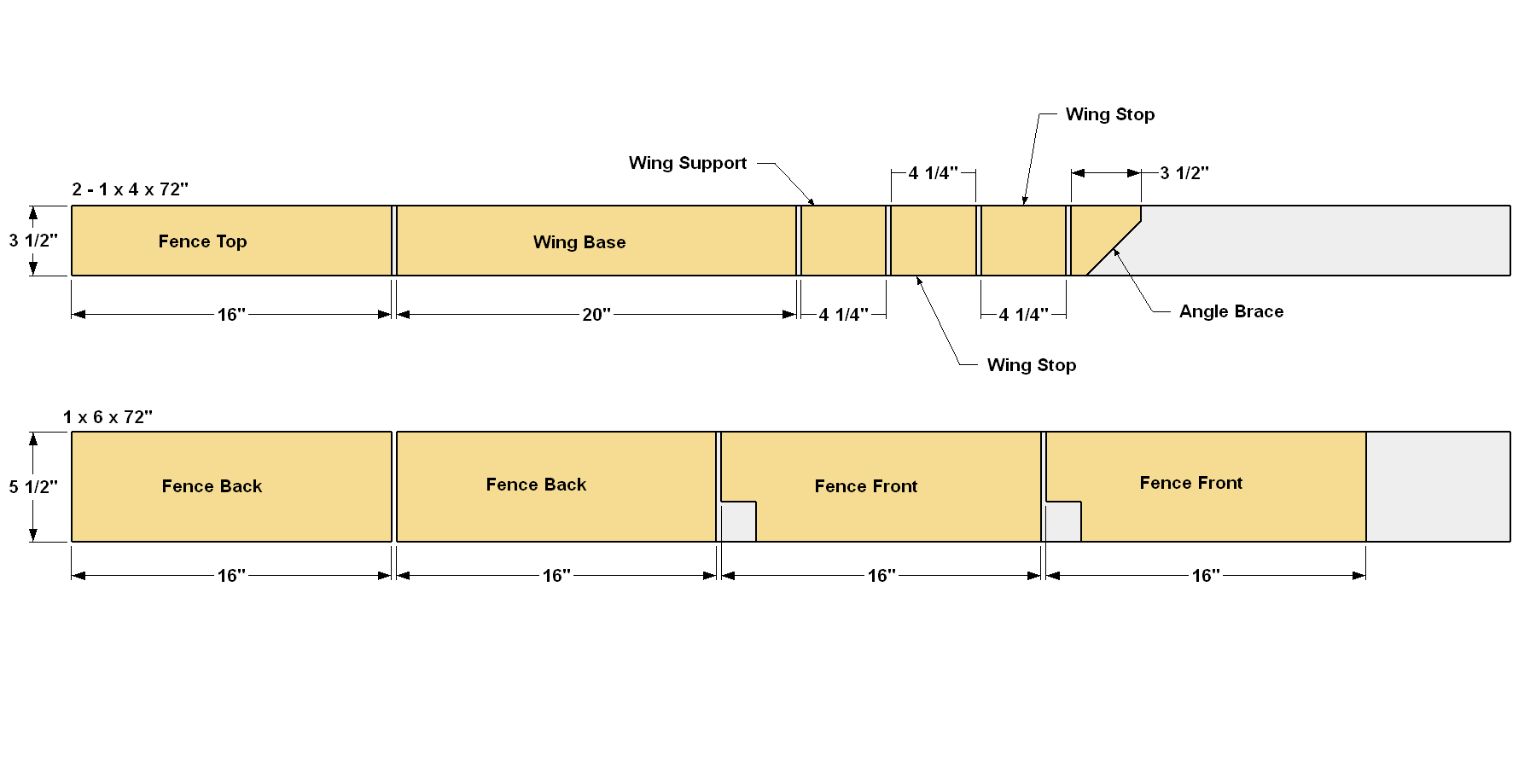
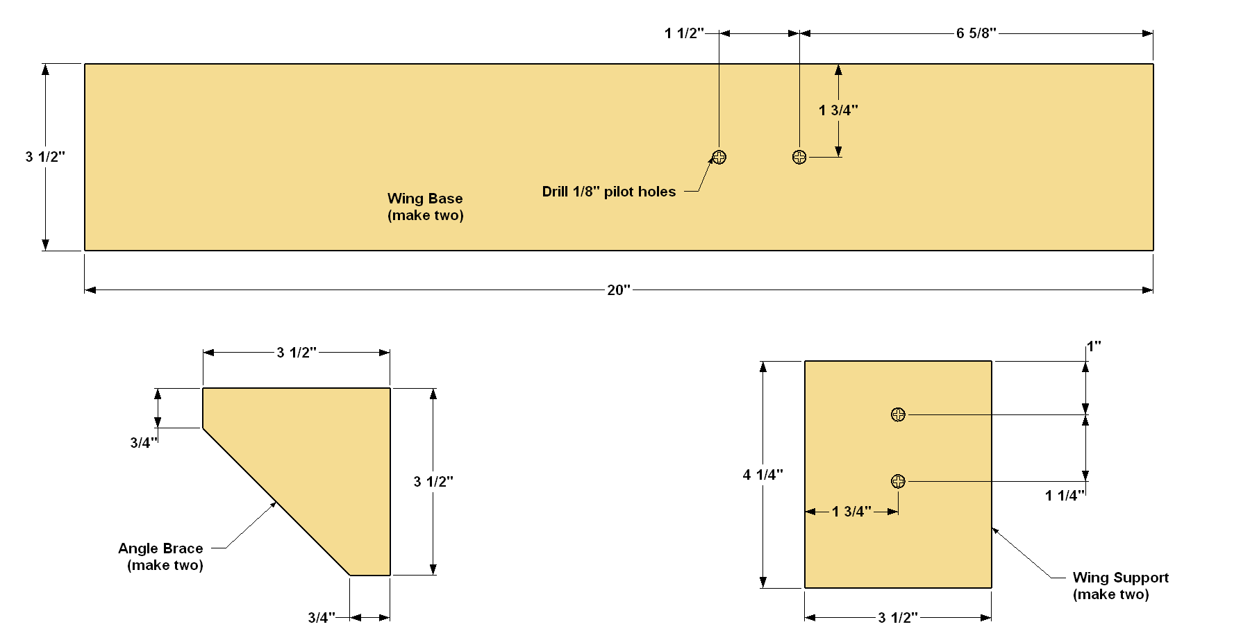
Cut the Wing Base, Support, and Brace
Cut two Wing Bases, two Wing Supports, and two Angle Braces from a 1x4 board, as shown in the cutting diagram. Next, drill a pair of 1/8" pilot holes in the Wing Supports, as well as in the Wing Base, at the locations shown.
-
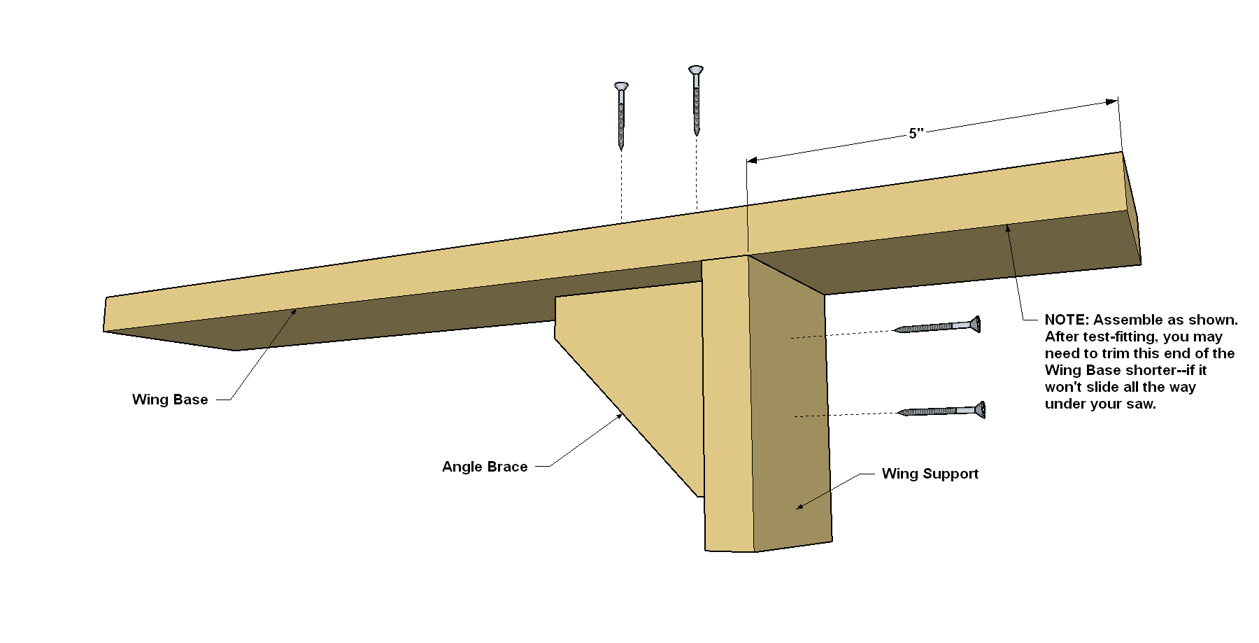
Assemble the Base, Support, and Brace
Now you can attach the Wing Support and Angle Brace to the Wing Base. Start by positioning the Wing Support as shown, making sure that it’s perpendicular to the edges of the Wing Base. Next, hold or clamp the Angle Brace in position. Using the 1/8" holes you drilled earlier, drill 1/16” holes into the Angle Brace. Then attach the Angle Brace using 1 1/4" flathead woodscrews. Repeat this process to create the other wing base assembly.
-
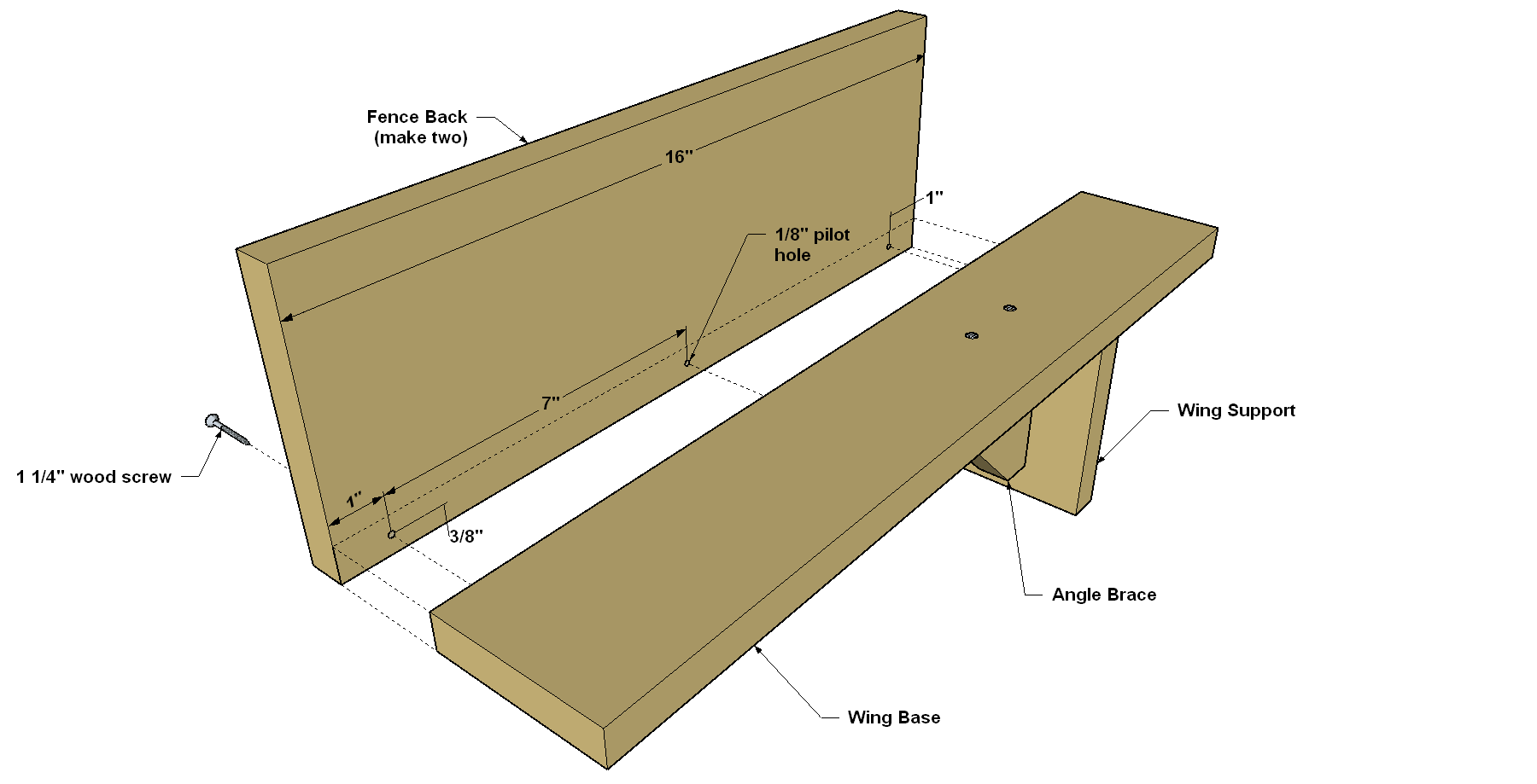
Cut and Attach the Fence Back
From a 1x6 board, cut two Fence Backs to length, as shown in the cutting diagram. Drill pilot holes in the Fence Back, as shown. Then align Fence Back with the base assembly, as shown. And attach the Fence Back using 1 1/4" flat-head wood screws. Repeat this to attach the other Fence Back.
-
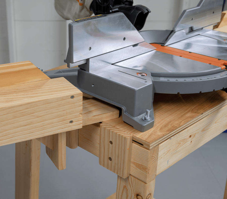
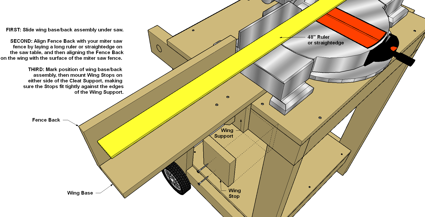
Align the Wing Assemblies
To provide a flat, straight fence surface, you need to align the Fence Backs with the fence on your miter saw. To do that, first slip one wing assembly under your saw, as shown. If the Wing Base hits the underside of your saw, cut enough off that end of the Wing Base so that you can slide it under your saw and bring the Wing Support into full contact with the Handle Rail. With that done, use a long ruler or reliable straightedge to align the Fence Back on the wing with your saw fence. Then clamp the Wing Support to the Handle Rail. Finally, cut Wing Stops to length, as shown in the cutting diagram. Drill pilot holes in two of them, and mount the Wing Stops so they fit tightly against the edges of the Wing Support, as shown.
-
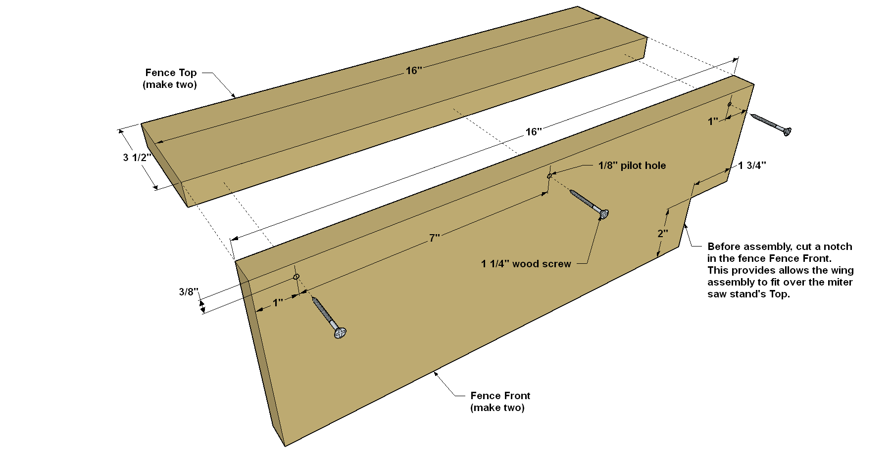
Make the Fence Front and Top
From a 1x4 board, cut the Fence Top to length, as shown in the cutting diagram. Then, from a 1x6 board, cut the Fence Front to length, as well. Using a jigsaw, notch one corner of each Fence Face, as shown. This will allow the Fence Face to slip over the miter saw stand’s top and fit closer to your saw. Drill 1/8" pilot holes in each Fence Face, as shown. Position the Fence Front against the Fence Base, as shown, and then attach it using 1 1/4"flat-head wood screws. Repeat for the other assembly.
-
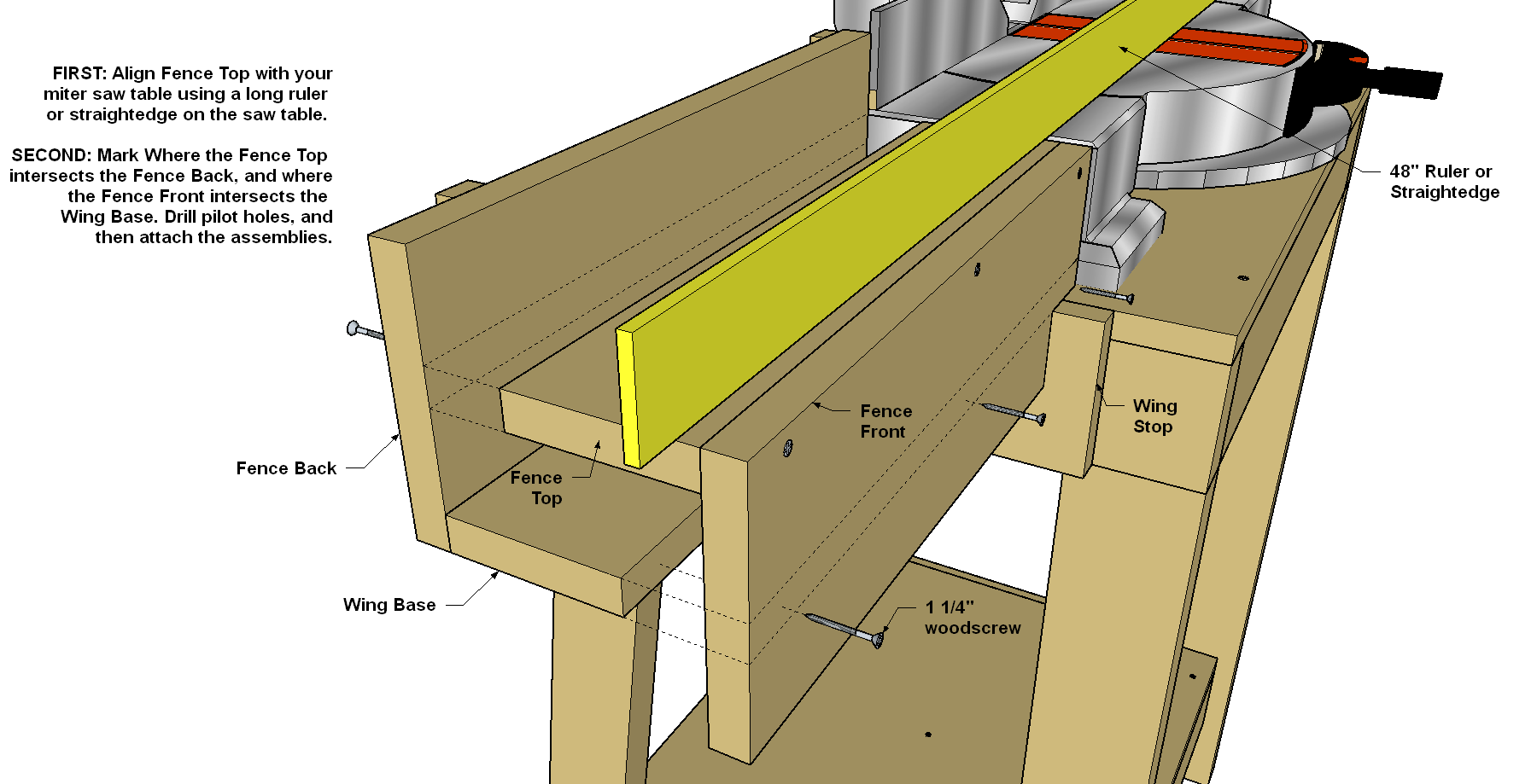
Align the Fence
Now you need to align the Fence Top so it’s level with your saw’s table surface. Use a long ruler or a reliable straightedge to align fence top/front assembly, as shown. Mark where the Fence Top intersects the Fence Back. Now mark where the Fence Front intersects the Wing Base. With that done, you can separate these assemblies. Lay out and drill pilot holes, and then attach the fence top/face assembly to the wing assembly. Repeat this to align the fence on the other side of your saw. The wings fit snug, but you may want to add a screw on either side of the Angle Brace that goes into the handle rail. If you want to remove the wings later, just remove these two screws in each wing.
With that, your miter saw station is ready to use. Before you put it to use, though, you may want to wipe on a coat of oil finish, like we did. This protects the wood and makes the miter saw station look great.